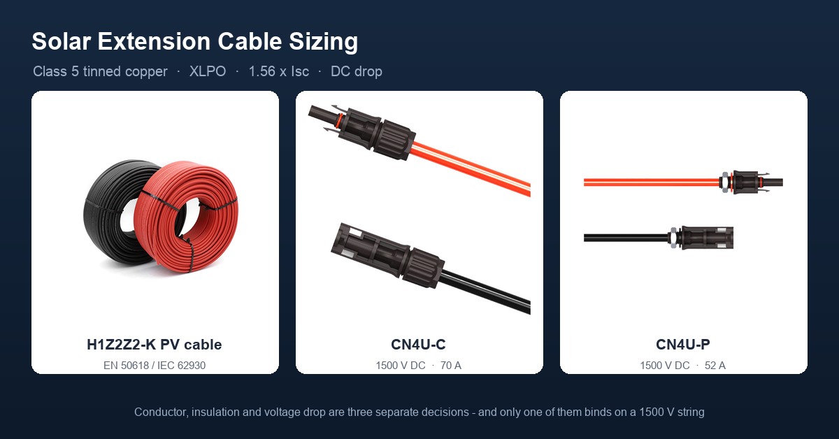
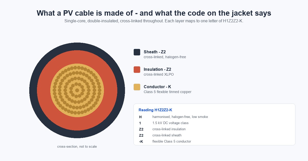
A solar extension cable is a single-core, double-insulated flexible cable used on the DC side of a photovoltaic system to close the distance between a module or string and the next connection point, whether that is a combiner box, an inverter or a battery bank. Four properties define it under EN 50618 and IEC 62930: a Class 5 tinned copper conductor, cross-linked halogen-free insulation and sheath, a rated DC voltage of 1.5 kV between conductors, and a continuous conductor temperature of 90 °C with a design life of at least 25 years. A cable that misses any one of those four is not a PV cable regardless of what the jacket is printed with.
The order matters as much as the values. Conductor size, insulation compound and voltage drop answer three different questions, and on a 1500 V string only one of them usually decides the result. Working from the standard forward, rather than backwards from a wire gauge chart, keeps those three decisions separate.
1. Where the cable sits, and why DC and AC are not interchangeable
A PV system has two electrical domains. The DC side runs from the module junction box through string cables, extension cables and combiners to the inverter DC input. The AC side runs from the inverter output to the distribution board and the grid interconnection.
EN 50618 and IEC 62930 both scope their cables to the DC side. The standards carry an AC rating of 0.6/1 kV, so a certified PV cable is not prohibited on an inverter output where local wiring rules permit it, but the default choice for AC output conductors remains a general-purpose building wire selected under IEC 60502 or the equivalent national code. The two domains are certified against different rules, and a cable selected for one should not be assumed compliant in the other.
The common claim that DC systems are inherently more efficient than AC systems because AC has higher resistance is not how the loss arises. Loss in the DC array is resistive, I²R in the conductor and at every termination. Loss on the AC side comes mostly from the conversion stage itself — one DC-to-AC conversion typically running 96 to 99 percent — plus the same resistive terms. Comparing the two by "resistance" misstates the reason.
2. Conductor: tinned copper Class 5, and why aluminium is not the answer
Copper at 20 °C conducts at 58.0 MS/m against roughly 35.5 MS/m for aluminium, so an aluminium conductor needs about 1.6 times the cross-section to match copper's resistance. That comparison is real, but it is not why aluminium is excluded from PV string wiring.
The exclusion is mechanical and chemical. Aluminium creeps under clamping pressure, forms a hard insulating oxide within minutes of exposure, and sets up galvanic corrosion wherever it meets copper or a tin-plated termination. MC4-type contacts are designed, tested and certified for copper conductors, and their crimp barrels are qualified against that geometry. EN 50618 requires flexible tinned copper to IEC 60228 Class 5 with individual strands tin-coated; there is no aluminium option within the standard's scope. Aluminium appears in PV projects, but on the AC collection network of large plants, with compression lugs and antioxidant compound at every termination.
Tinning is not cosmetic. Strand-level plating slows oxidation in humid and coastal atmospheres and stabilises the contact interface inside a crimp barrel, which is where most long-term resistance drift begins. Standard sizes under EN 50618 and IEC 62930 run 1.5, 2.5, 4, 6, 10, 16, 25 and 35 mm²; anything below 1.5 mm² sits outside the standard.
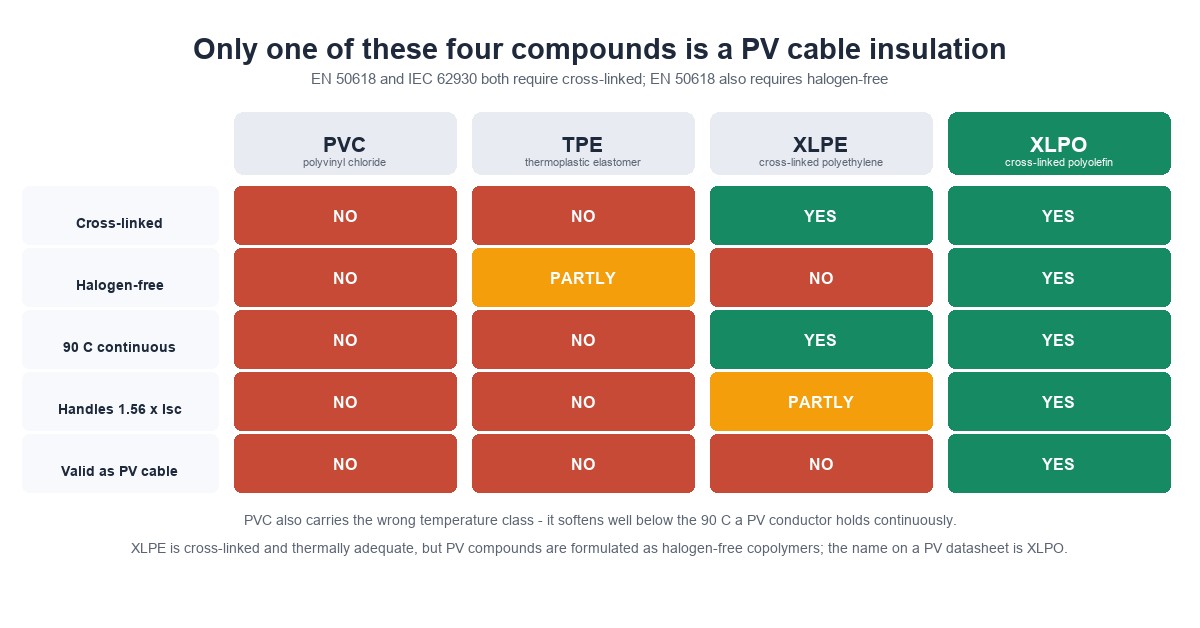
3. Insulation: XLPO, not XLPE, and definitely not TPE or PVC
Both standards require cross-linked insulation and sheath. The compound used in practice is XLPO, a halogen-free cross-linked polyolefin, most often cross-linked by electron-beam irradiation.
Cross-linking changes the material from thermoplastic to thermoset. Before cross-linking the polymer softens and flows when heated; after cross-linking the molecular network holds its shape. That is what allows a conductor rated 90 °C continuous to survive 120 °C for a cumulative 20 000 hours and 250 °C for five seconds under short circuit, and what lets a thin-walled cable pass long-term UV and ozone exposure without the surface chalking that destroys non-cross-linked jackets.
Three materials appear in specifications where they should not:
- TPE is a thermoplastic elastomer. Flexible and UV-stabilisable, but not cross-linked, so it cannot satisfy the hot-set requirements of either standard.
- XLPE is cross-linked polyethylene. Thermally adequate, but PV compounds are formulated as halogen-free polyolefin copolymers to meet flexibility, halogen-free and flame requirements together. "XLPE" on a PV datasheet is imprecise at best.
- PVC contains halogens, loses plasticiser under UV and embrittles, and is rated far below the 90 °C conductor temperature PV cable has to hold.
One standard difference is worth carrying into the specification: IEC 62930 permits both halogen-free and halogen-containing cables, while EN 50618 permits halogen-free only. A project in Europe, or one with enclosed-roof or carport runs, should specify EN 50618 to lock in halogen-free behaviour. The material comparison and the H1Z2Z2-K code are covered in more depth in why H1Z2Z2-K is the PV cable standard.
4. Ratings that actually appear on a datasheet
| Parameter | EN 50618 / IEC 62930 | UL 4703 | Note |
|---|---|---|---|
| Rated voltage | AC 1.0/1.0 kV; DC 1.5/1.5 kV (Umax 1.8 kV) | 600 V, 1000 V or 2000 V | A 1500 V system normally uses the 2000 V class under UL 4703 |
| Test voltage | 6.5 kV AC, 5 min | per UL schedule | Verifies insulation integrity, not operating margin |
| Continuous conductor temperature | 90 °C | 90 °C | Baseline for ampacity tables |
| Overload temperature | 120 °C, limited to 20 000 h cumulative | per UL schedule | An endurance budget, not a working temperature |
| Short-circuit temperature | 250 °C, max 5 s | per UL schedule | Sets fault-withstand behaviour |
| Ambient range | −40 °C to +90 °C | −40 °C to +90 °C | Installation generally not below −20 °C |
| Design life | ≥ 25 years by thermal endurance (EN 60216) | per UL schedule | 30-year claims need a manufacturer endurance report |
| Water | AD8 water resistance (EN 62440), impact-tested for direct burial | per UL schedule | Water rating for cable; IP rating belongs to connectors |
| Fire | IEC/EN 60332-1-2 flame; IEC/EN 60754 halogen; IEC/EN 61034 smoke | UL 4703 VW-1 or equivalent | EN 50618 requires halogen-free; IEC 62930 does not |
| Standard | Role |
|---|---|
| EN 50618 | European product standard, H1Z2Z2-K, halogen-free mandatory |
| IEC 62930:2017 | International equivalent, 1.5 kV DC, halogen-free or halogenated |
| IEC 60228 | Conductor classes; Class 5 flexible applies to PV cable |
| TÜV 2 PfG 1169 | Legacy PV1-F specification, superseded by EN 50618 |
| UL 4703 | North American PV wire |
| IEC 62852 | Connectors for PV systems, the mating half of the cable |
| IEC 60529 | IP codes, applies to connectors, not to cable |
5. Sizing step one: conductor ampacity at 1.56 × Isc
Two multipliers apply in sequence in NEC 690.8. The first, 1.25, accounts for irradiance above the 1000 W/m² standard test condition, which raises string current above the nameplate Isc. The second, 1.25, accounts for continuous operation. The product is 1.56.
Required conductor ampacity ≥ Isc × 1.25 × 1.25 = 1.56 × Isc
For a module with Isc of 14 A, common on current large-format TOPCon and HJT products, the conductor must carry 21.8 A before any derating. Where several strings land in parallel on the same input, the calculation is per string, not for the combined total.
Ampacity is then derated for the installation. Published free-air values from a representative H1Z2Z2-K datasheet, before derating:
| Cross-section | Typical free-air ampacity | Max DC resistance at 20 °C |
|---|---|---|
| 1.5 mm² | 30 A | 13.7 Ω/km |
| 2.5 mm² | 41 A | 8.21 Ω/km |
| 4 mm² | 55 A | 5.09 Ω/km |
| 6 mm² | 70 A | 3.39 Ω/km |
| 10 mm² | 98 A | 1.95 Ω/km |
| 16 mm² | 132 A | 1.24 Ω/km |
| 25 mm² | 176 A | 0.795 Ω/km |
| 35 mm² | 218 A | 0.565 Ω/km |
| Ambient | 30 °C | 40 °C | 50 °C | 60 °C | 70 °C |
|---|---|---|---|---|---|
| Derating factor | 1.00 | 0.91 | 0.82 | 0.71 | 0.58 |
A rooftop run in conduit at 60 °C drops a 4 mm² conductor from 55 A to about 39 A, before any bundling correction. Add a second correction where several cables share a tray or conduit with restricted airflow. The 4 mm² versus 6 mm² decision, and the cases where it flips, is worked through in PV DC cable sizing: 4 mm² vs 6 mm² vs 10 mm².
6. Sizing step two: voltage drop, and when it actually binds
Voltage drop across a two-conductor DC circuit is:
ΔV = I × R′ × 2L ÷ 1000
where I is the circuit current in amperes, R′ is the conductor resistance in Ω/km, and L is the one-way length in metres. The factor of two accounts for the return conductor. Working in mV per ampere per metre of loop length simplifies the arithmetic:
| Cross-section | Loop mV/A/m at 20 °C | Loop mV/A/m at 70 °C |
|---|---|---|
| 1.5 mm² | 27.4 | 32.8 |
| 2.5 mm² | 16.4 | 19.6 |
| 4 mm² | 10.2 | 12.2 |
| 6 mm² | 6.8 | 8.1 |
| 10 mm² | 3.9 | 4.7 |
| 16 mm² | 2.5 | 3.0 |
| 25 mm² | 1.6 | 1.9 |
| 35 mm² | 1.1 | 1.3 |
Copper resistance rises about 0.393 percent per °C, so a conductor operating at 70 °C carries roughly 1.20 times its 20 °C resistance. Skipping that correction understates drop by a fifth in hot climates.
On the threshold: the 3 percent figure quoted for DC circuits comes from NEC guidance for AC branch circuits. PV DC design practice targets 1 to 2 percent from array to inverter, with 3 percent treated as the outer limit.
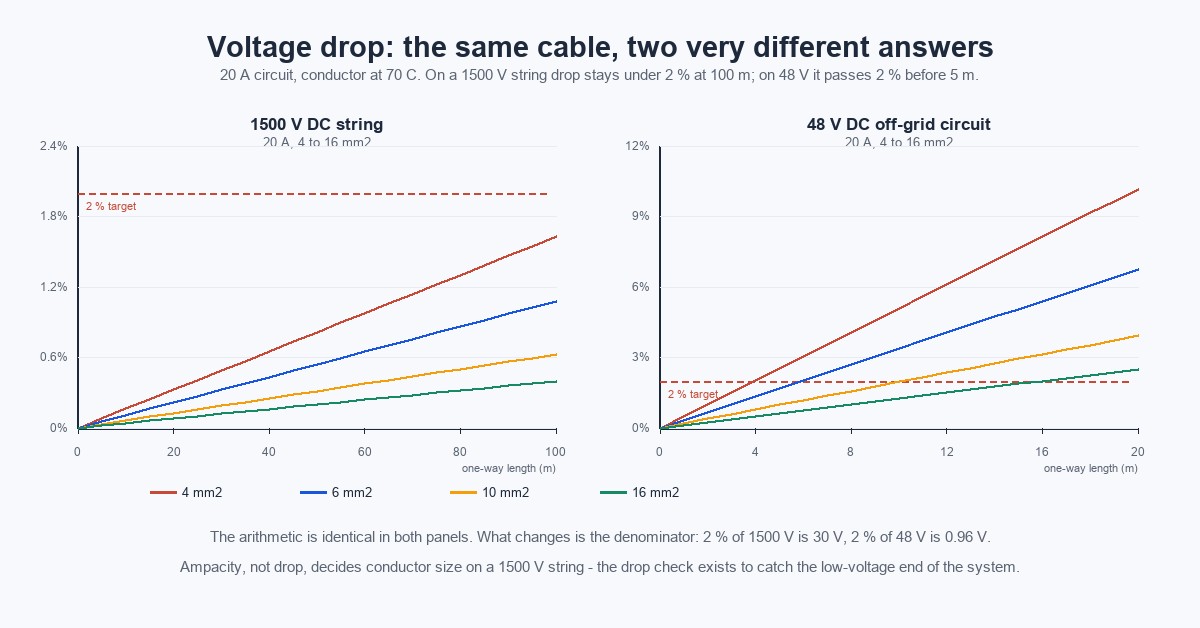
The consequence changes how much of the sizing exercise matters. On a 1000 V or 1500 V string, voltage drop is rarely the binding constraint. A 60 m run of 4 mm² carrying 18.7 A loses about 11.4 V, which is 0.76 percent of 1500 V. Ampacity and the connector's current rating govern that decision. Voltage drop binds where the system voltage is low: 12 V, 24 V and 48 V off-grid circuits and the cable between a battery bank and an inverter, where 2 percent of the system voltage is under a volt.
7. Worked example: a 48 V array at 15 m
Take a 48 V off-grid array rated 1000 W, located 15 m from the inverter. Operating current is 1000 ÷ 48 = 20.8 A. Checking the arithmetic across three conductor sizes:
- 2 AWG, 33.6 mm²: drop = 20.8 A × 1.0 mV/A/m × 15 m ≈ 0.31 V, or 0.65 percent of 48 V
- 6 AWG, 13.3 mm²: drop = 20.8 A × 2.6 mV/A/m × 15 m ≈ 0.81 V, or 1.7 percent of 48 V
- 8 AWG, 8.37 mm²: drop = 20.8 A × 4.1 mV/A/m × 15 m ≈ 1.28 V, or 2.7 percent of 48 V
Against a 2 percent target, 6 AWG is the answer. 2 AWG uses about 2.5 times the copper for no measurable gain, and it forces a larger bending radius and heavier termination hardware on the installer. Oversizing is safe in the electrical sense and wasteful in every other sense.
The same example needs an ampacity check that the voltage drop calculation does not perform. If the array's Isc is 26 A, the conductor must be rated for 1.56 × 26 = 40.6 A before derating. 6 AWG clears that comfortably; a thinner conductor chosen on voltage drop alone might not. On low-voltage circuits the two checks are both live, which is why they belong together.
8. Water, UV and burial: rating the right component
Cable and connector are rated under different systems, and conflating them produces specifications that cannot be satisfied.
The cable's water performance is expressed as AD8 water resistance under EN 62440, with impact testing that qualifies it for direct burial. The connector's ingress protection is an IP code under IEC 60529, typically IP67 or IP68 when mated. That protection exists only in the mated state. An unmated MC4 connector sits around IP2X, which is why loose connectors lying in a tray or on a roof during installation are the most common source of water ingress at energisation.
UV resistance is verified by standardised weathering tests rather than by material name alone, with ozone resistance checked separately. For coastal projects, tin-plated conductors and a sheath with documented salt-mist performance matter more than any single UV claim, and any such claim should reference the test method rather than assert it.
9. The connector half of the circuit
An extension cable is only as reliable as the terminations at each end. Three rules cover most of what goes wrong in the field.
Match the conductor to the contact. Standard MC4-type contacts terminate 4 mm² and 6 mm² directly. 10 mm² usually needs a larger contact or a dedicated variant, and an undersized barrel produces a crimp that passes a pull test and fails thermally.
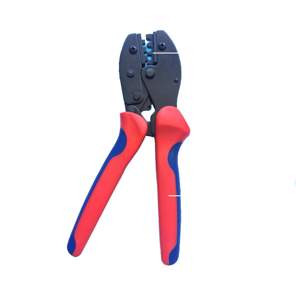
Crimp with the right tooling. A ratchet crimper with a die matched to the specific contact and conductor size is required. Pliers and non-ratcheting tools do not produce a gas-tight crimp; the joint oxidises, resistance rises, and the connector heats under load. Cable gland nuts are torqued to roughly 2 to 3 N·m, or to the manufacturer's figure where one is published. The full assembly sequence is documented in PV cable installation.
Do not mix brands. NEC 690.33(C) and UL 6703 both require connectors to be mated only with the same manufacturer's type, or with a type specifically evaluated and listed for intermating. Contact geometry, spring force and material pairing differ between brands, and mismatched pairs are a documented cause of roof fires alongside poor crimps. The interface itself is explained on the MC4-compatible connector page.
10. How a cable run fails
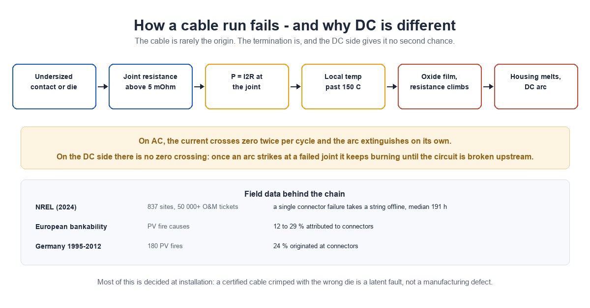
The failure chain is consistent enough to be predictable, and it almost never starts in the cable.
A termination with elevated contact resistance dissipates P = I²R at the joint. A 50 mΩ joint carrying 8 A dissipates 3.2 W in a volume the size of a fingertip, which drives local temperature past 150 °C. Heat accelerates oxidation, oxidation raises resistance further, and the loop runs away until the housing melts and the conductors arc. On the DC side there is no current zero crossing, so once an arc strikes it does not self-extinguish the way an AC arc does.
Field data gives the failure mode its weight. An NREL analysis published in 2024, covering 837 sites and more than 50 000 O&M tickets, found that a single connector failure takes a string offline with a median downtime of 191 hours. European bankability reporting attributes 12 to 29 percent of PV fires to connectors. Of 180 PV fires recorded in Germany between 1995 and 2012, 24 percent originated at connectors.
Most of that is decided at installation, not at the factory. A certified cable crimped correctly into a matched certified connector outlasts the modules. The same cable crimped with the wrong die is a latent fault that passes every visual check.
11. Acceptance checks before energisation
| Check | Method | Acceptance |
|---|---|---|
| Crimp geometry | Visual, manufacturer die | Barrel fully formed, conductor visible at inspection window, no stray strands |
| Pull test | Spring balance or calibrated rig | ≥ 50 N per IEC 62852; site practice commonly 310 N or higher |
| Contact resistance | Four-wire milliohm meter | ≤ 0.5 mΩ new; under 1 mΩ in service; above 5 mΩ investigate |
| Insulation resistance | 500 V DC megger, dry conditions | ≥ 100 MΩ |
| Gland torque | Torque screwdriver | 2 to 3 N·m, or manufacturer's figure |
| Polarity and labelling | Visual | Positive and negative identified at both ends; jacket colour consistent |
| Routing | Visual | Bend radius at least 4 to 6 times overall diameter; UV-stable ties; no standing water; DC and AC separated |
The test regime behind those acceptance values, and the failure modes a type test cannot catch, are covered in PV connector testing.
12. Selection matrix
| Application | System voltage | Typical conductor | Connector | Governing constraint |
|---|---|---|---|---|
| Residential rooftop string | 1000 V | 4 mm² | MC4-compatible, 1500 V | Ampacity at 1.56 × Isc after ambient derating |
| Residential, high-current modules | 1000–1500 V | 6 mm² | MC4-compatible, 1500 V | Isc of 18 A and above |
| Commercial string to combiner | 1500 V | 6 mm² | MC4-compatible, 1500 V | Voltage class and ampacity |
| Combiner to inverter trunk | 1500 V | 10 mm² and above | Larger-contact variant | Combined string current, bend radius |
| Off-grid array to controller | 24–48 V | Sized on drop | MC4-compatible | Voltage drop at 1–2 percent |
| Battery to inverter | 12–48 V | Sized on drop | Lug or bolted | Voltage drop, short-circuit current |
| Portable and RV | 12–48 V | 4 mm² flexible | MC4-compatible | Flexibility, UV, storage handling |
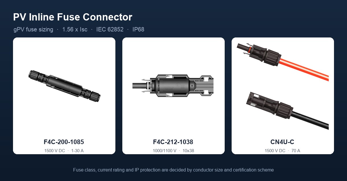
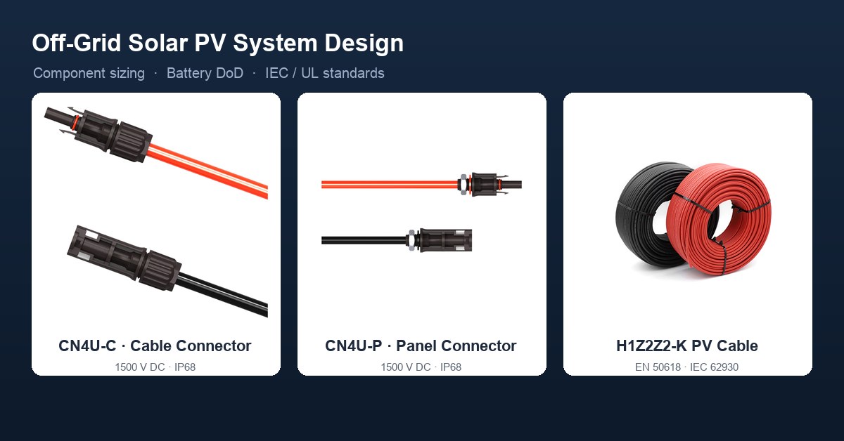
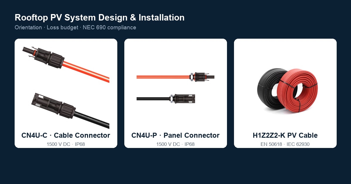
Treasol manufactures to the specifications described above: H1Z2Z2-K solar PV cable for DC side runs, the CN4U-C cable connector and CN4U-P panel connector rated 1500 V and IP68 in the mated state, with the full PV cable range covering 1.5 to 35 mm². Ready-made assemblies are specified in custom PV extension cables, and the crimp and assembly process is documented on the PV connector manufacturing page.
FAQ
What size solar extension cable do I need for a residential string?
Start from the module short-circuit current and multiply by 1.56, applying NEC 690.8. A module with Isc of 14 A needs a conductor rated for at least 21.8 A after derating, which 4 mm² satisfies in most rooftop conditions. Move to 6 mm² for longer runs, high ambient temperatures, conduit with restricted airflow, or where the array will be expanded later.
Is 4 mm² or 6 mm² the better default for PV cable?
4 mm² remains the most common residential string conductor. 6 mm² is the safer default where modules exceed roughly 18 A Isc, where runs are long, or where the roof reaches 60 °C or more. The cost difference per metre is small compared with the cost of a return visit.
Can I use aluminium cable for a solar PV system to reduce cost?
Not on the PV string DC side. MC4-type contacts are qualified for copper conductors, and aluminium's creep, oxide formation and galvanic behaviour make the termination unreliable. EN 50618 requires flexible tinned copper conductors to IEC 60228 Class 5. Aluminium appears on AC collection networks with compression lugs and antioxidant treatment.
Why is PVC cable not acceptable for solar installations?
PVC contains halogens, loses plasticiser under UV and becomes brittle, and is not rated for a 90 °C continuous conductor temperature. EN 50618 and IEC 62930 require cross-linked halogen-free compounds, which in practice means XLPO, a halogen-free cross-linked polyolefin.
What is the correct voltage drop limit on the PV DC side?
Design to 1 to 2 percent from array to inverter, with 3 percent as the outer limit. The 3 percent figure often quoted comes from NEC guidance for AC branch circuits. On 1000 V and 1500 V strings, voltage drop is rarely the binding constraint; on 12, 24 and 48 V off-grid and battery circuits it usually is.
Does IP68 mean a solar connector is waterproof at all times?
No. IP68 under IEC 60529 applies in the mated state. An unmated MC4 connector sits around IP2X, and cable water performance is expressed separately as AD8 water resistance under EN 62440. Open connectors left exposed during installation are a common source of moisture ingress.
Can I connect a cable from one brand to a connector from another brand?
No. NEC 690.33(C) and UL 6703 require mating within the same certified type, or a combination specifically evaluated and listed for intermating. Contact geometry, spring force and material pairing differ between brands, and mismatched pairs are a documented contributor to connector fires alongside poor crimping.
How long should a solar extension cable last?
25 years is the design life established by thermal endurance testing under EN 60216. Claims beyond that should be backed by a manufacturer endurance report rather than a marketing figure.
References
- EN 50618 — Electric cables for photovoltaic systems (H1Z2Z2-K), harmonised designation and requirements
- IEC 62930:2017 — Electric cables for photovoltaic systems with a voltage rating of 1.5 kV DC; 90 °C continuous, 120 °C limited to 20 000 h
- IEC 60228 — Conductors of insulated cables; Class 5 flexible conductors
- IEC 62852:2019 — Connectors for DC application in photovoltaic systems; safety requirements and tests
- UL 4703 — Photovoltaic Wire; voltage classes 600 V, 1000 V and 2000 V
- UL 6703 — Connectors for use in photovoltaic systems
- TÜV 2 PfG 1169/08.2007 — PV1-F cable specification, superseded by EN 50618
- IEC 60529 — Degrees of protection provided by enclosures (IP code)
- EN 62440 — Electric cables with a voltage rating not exceeding 450/750 V; AD8 water resistance classification
- IEC/EN 60332-1-2 — Flame propagation test for a single insulated wire or cable
- IEC/EN 60754-1/2 — Halogen acid gas evolution and acidity during combustion
- IEC/EN 61034-1/2 — Measurement of smoke density
- EN 50396 / HD 605/A1 — Ozone and UV resistance test methods for cable compounds
- EN ISO 4892-1/3 — Accelerated laboratory weathering exposure methods
- EN 60216 — Thermal endurance properties of insulating materials; basis for the 25-year design life
- IEC 60364-5-52 — Selection and erection of wiring systems; ampacity and derating methods
- IEC 60364-7-712 — Requirements for solar photovoltaic power supply systems
- NFPA 70 (NEC) Article 690 — 690.8 circuit sizing, 690.31 wiring methods, 690.33 connector mating
- IEC 63265:2021 — Fire safety and DC arc-risk requirements for photovoltaic systems
- NREL (2024) — analysis of connector and balance-of-system failure across 837 sites and 50 000 O&M records; median downtime 191 hours per connector failure
- European bankability reporting on PV fire causes; 12 to 29 percent attributed to connectors
- German PV fire statistics, 1995–2012; 180 fires, 24 percent originating at connectors
Prepared by Treasun New Energy Technology Co., Ltd — manufacturer of MC4-compatible PV connectors, fuse connectors, junction boxes, wiring harnesses and H1Z2Z2-K photovoltaic cable.