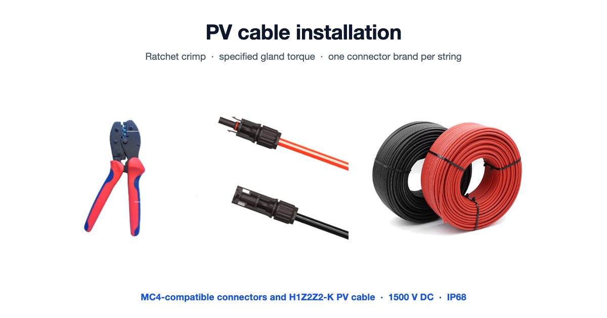
A PV DC cable is only as reliable as the joint at each end. Most field failures do not begin in the cable; they begin in a connector that was crimped by feel, torqued by hand or mixed across brands. IEC 62852 and NEC Article 690 define what that joint has to do, and none of it is proven by the click.
The connector is usually the cheapest part in the array and the one most often assembled without a torque value, a matched die or a resistance reading. What separates a certified joint from a merely working one is a short list of measurable steps.
1. First, the naming: what "MC4" actually means
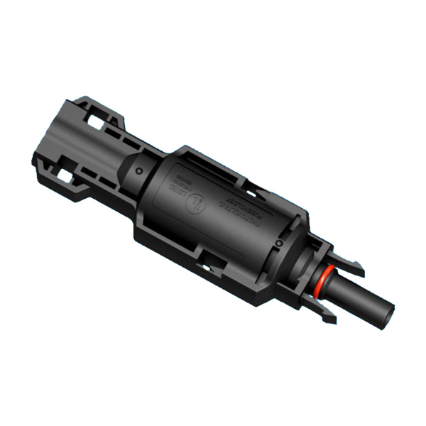
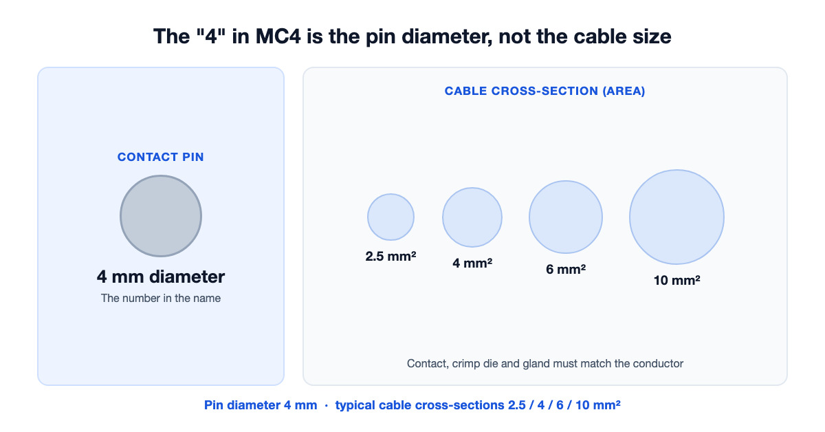
The connector being installed is an MC4, originally the Stäubli Multi-Contact. The "4" is the 4 mm contact pin diameter. It has nothing to do with the 4 mm² cable cross-section that installers new to the hardware often assume. The contact, crimp die and cable gland are matched to a wire size, and MC4-compatible parts are built for several of them: commonly 2.5, 4, 6 and 10 mm². A 4 mm² contact on a 6 mm² conductor, or the reverse, gives an under- or over-compressed crimp and has to be rejected.
Every MC4-compatible connector placed in a PV system should carry a valid certificate to IEC 62852 (international) or UL 6703 (North America), and the cable it terminates should be H1Z2Z2-K / EN 50618 / IEC 62930 cross-linked, halogen-free PV wire. A "solar connector" with no stated standard is not bankable.
2. Tools and materials (with the specs that matter)
| Item | Specification |
|---|---|
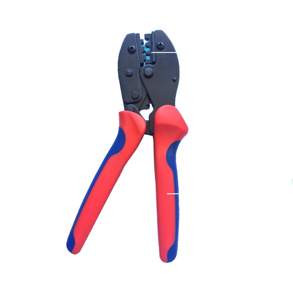
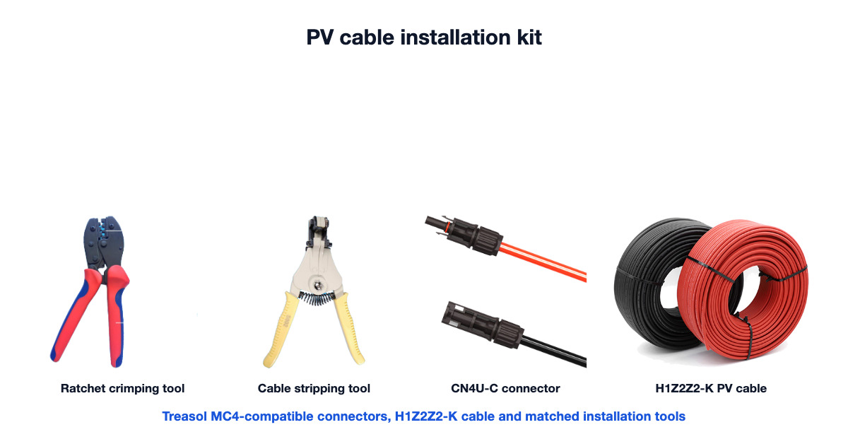
| Crimp tool | Ratchet tool with a die matched to the contact size and wire cross-section (not slip-joint pliers, not generic wire crimpers) |
| Wire stripper | Set to the manufacturer's strip length (typically 13–15 mm conductor, 50–60 mm outer jacket) |
| Torque tool | For the cable gland nut, typically 2–3 N·m |
| Unlocking tool | Required to separate mated pairs safely |
| Cable | H1Z2Z2-K (EN 50618 / IEC 62930), tinned copper, Class 5 per IEC 60228 |
| Connectors | One brand throughout the string, rated for the system voltage (1000 V or 1500 V DC) |
3. Step-by-step assembly (to standard, not to feel)
3.1 Strip to spec
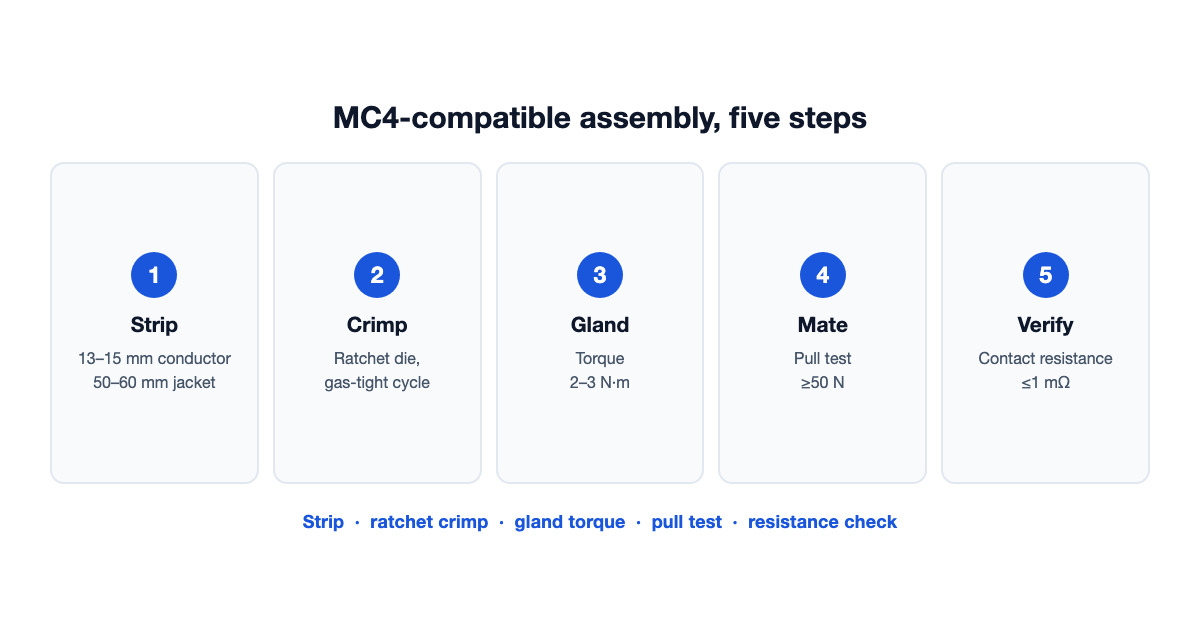
Remove the outer jacket to the specified length and strip the conductor insulation to the exact dimension in the connector's instruction sheet, commonly 13–15 mm. Do not nick the strands; broken strands reduce the effective cross-section and raise resistance. Over-stripping leaves bare conductor inside the housing and can defeat the gland seal.
3.2 Crimp with the correct die
Insert the conductor fully into the contact barrel. The strands should be visible in the inspection hole. Crimp with the ratchet tool and let the cycle complete before the tool releases. A gas-tight crimp closes the air gaps between strands and barrel, and that is what prevents the oxidation that drives long-term resistance drift. A partial crimp from non-ratcheting pliers starts to oxidise within months.
3.3 Assemble the housing and torque the gland
Thread the gland nut and seal onto the cable before seating the contact; they cannot be added afterwards. Push the crimped contact into the housing from the cable-entry end until it latches. A correctly seated contact cannot be pulled out by hand. Tighten the gland nut to the manufacturer's torque, typically 2–3 N·m. Hand-tight is not enough: the gland compresses the seal to reach IP67/IP68, and an under-torqued nut lets moisture wick in at the first rain.
3.4 Mate and verify mechanically
Push the male and female halves together with firm, even pressure until the locking tabs click. Confirm engagement by trying to separate them by hand; a correctly locked pair needs the MC4 unlocking tool to come apart. Then perform a pull test at the force specified in IEC 62852 (minimum 50 N, with field practice for 4 mm² often at or above 310 N) and confirm the joint does not separate. On commercial jobs, record the result as part of commissioning.
3.5 Verify electrically
Measure contact resistance across the mated pair with a low-resistance ohmmeter. A correctly assembled connection reads ≤1 mΩ including the cable contribution. A reading above 5 mΩ points to an insufficient crimp, incomplete mating or a cross-brand mismatch, and it has to be fixed before energising. "It clicked" is not a substitute for this measurement.
4. Routing and mechanical protection
- Minimum bending radius: at least 60 mm on module junction-box leads to the racking (per module install manuals), or roughly 8× the cable diameter on general runs. Sharp bends stress both the conductor and the XLPO insulation.
- Secure, don't sag: fix cable with UV-stabilised clips or stainless/PVDF ties at the manufacturer's spacing, commonly every 1.2–1.8 m on horizontal runs. Standard nylon ties go brittle in sunlight.
- Strain relief and separation: use strain-relief fittings at inverter and combiner inputs, and keep DC and AC conductors separated as the code requires, both to avoid induced faults and to keep troubleshooting manageable.
- Avoid water traps: never locate connectors where water can collect, and shield exposed connectors from uninterrupted sun where the design allows.
5. Grounding (NEC Article 690)
All exposed conductive parts, including module frames, racking, junction boxes and combiner enclosures, must be bonded to an equipment grounding conductor (EGC) per NEC 690.43, with system grounding under 690.41. Module frames are typically bonded with 4–14 mm² copper conductors at the IEC 61730-1 marked points. In North America, grounding hardware has to be listed to UL 467 / UL 2703. Grounding is not optional even with Class II modules, and frames must not be drilled with extra holes, which voids the module warranty.
6. The safety red lines
- One brand per string. NEC 690.33(C) and UL 6703 require connectors from a single manufacturer within a circuit. A pin from brand A in a housing from brand B may click together but will not hold certified contact pressure, and that is the leading cause of field arc faults.
- Never connect or disconnect under load. MC4-compatible connectors are not load-break rated. Shut the inverter down and confirm zero current first.
- Match the voltage rating. A 1000 V connector used in a 1500 V system may not interrupt a DC arc safely. Specify 1500 V-rated connectors for 1500 V systems.
- Rapid shutdown. Building-mounted systems in jurisdictions following NEC 690.12 must reduce conductor voltage to the controlled level within 30 seconds of a shutdown command.
7. Why a bad crimp burns: the failure chain
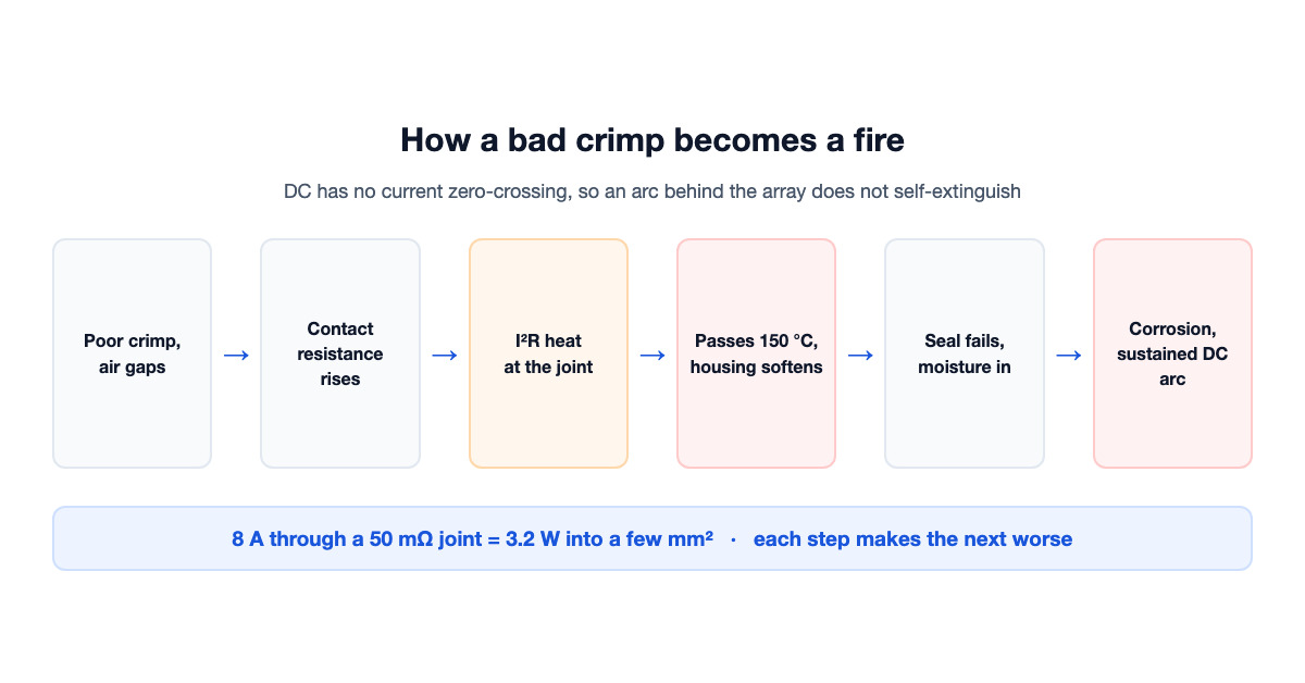
DC does not self-extinguish the way AC does. With no current zero-crossing, an arc that ignites behind the array can sustain for hours. A poor crimp is what starts it. Raised contact resistance turns the joint into a small heater, and the heat it dissipates follows P = I²R. At just 8 A through a 50 mΩ joint that is 3.2 W concentrated into a few square millimetres. Locally, that is enough to pass 150 °C, soften the housing, break the seal, admit moisture, accelerate corrosion and lift the resistance further. Each effect feeds the next.
The field statistics match the mechanism. Connectors have been implicated in 24–27 % of solar-related fires in Europe and in 24 % of 180 PV fires in Germany (1995–2012). A 2024 NREL study covering more than 50,000 O&M tickets across 837 U.S. sites found that each connector failure takes a full string offline, with a median repair downtime of 191 hours. The MC4 is a low-cost part, and done wrong it can take a multimillion-dollar array with it, along with any insurance cover.
8. Commissioning and maintenance
- Thermal inspection: scan every accessible MC4 with an infrared camera under at least 80 % rated load. A healthy joint runs within 3–5 °C of its neighbours. A 10–20 °C rise is a pre-failure condition; more than 20 °C above ambient is an immediate isolate-and-replace item.
- Visual checks: discolouration, cracked boots, connectors that separate by hand without the unlocking tool, or any melting or carbonisation all mean replacement.
- Reuse with care: contacts are rated for a minimum number of mating cycles (≥500 per IEC 62852). A connector pulled from service should be checked for wear, housing damage and O-ring condition before it is mated again.
9. Treasol products referenced
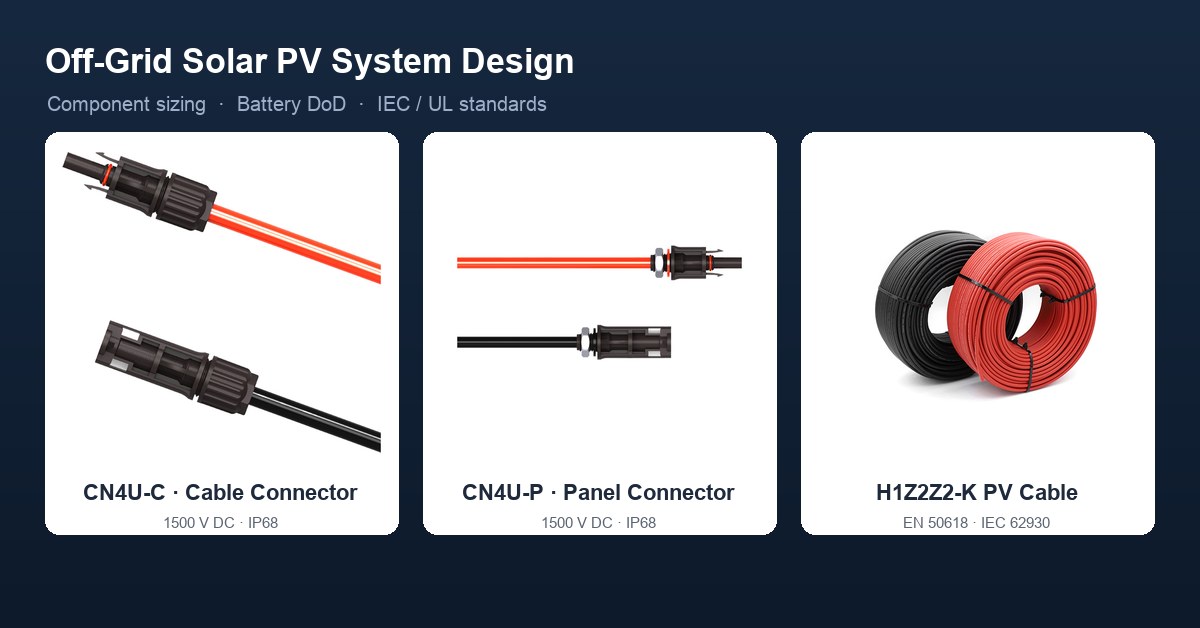
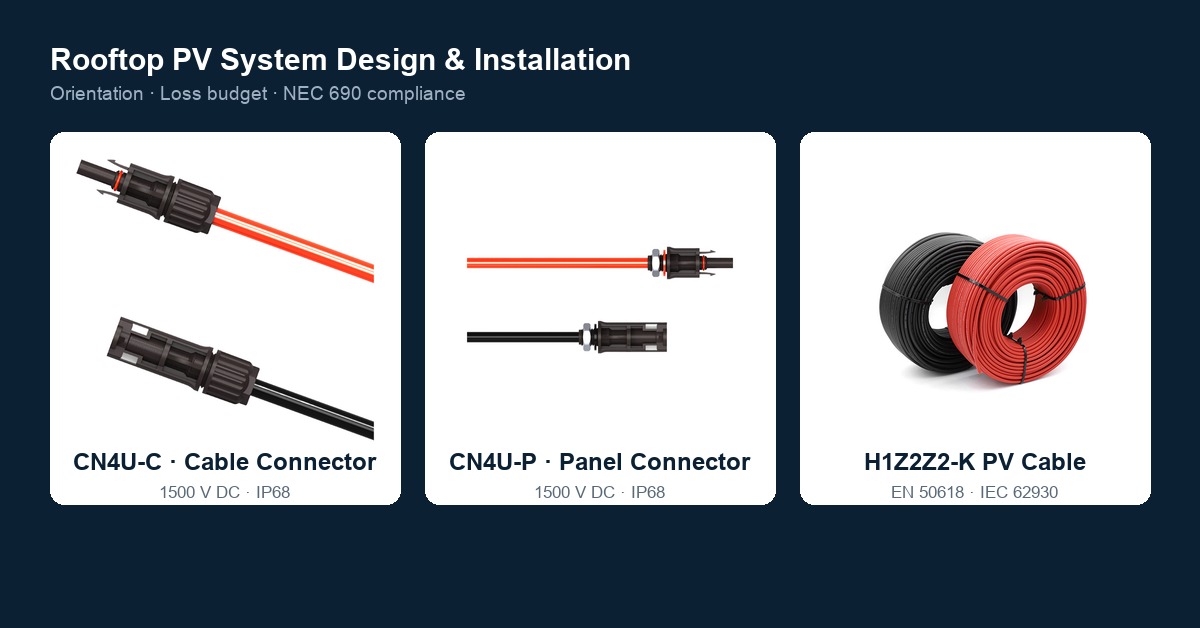
Treasol's CN4U-C cable connector and CN4U-P panel connector are MC4-compatible, rated 1500 V DC and IP68, and are made to be crimped with a matched ratchet die. They terminate the H1Z2Z2-K photovoltaic DC cable (EN 50618 / IEC 62930), stocked from 2.5 to 16 mm² in red and black within the PV cable category. For the mating and cross-brand rules behind section 6, see the MC4-compatible solar connector guide, and for how the contacts and housings are produced, the PV connector manufacturing process.
10. Frequently Asked Questions
What does 'MC4' stand for, and does it mean 4 mm² cable?
MC4 is the Stäubli Multi-Contact connector, and the "4" is the 4 mm contact pin diameter, not the cable size. MC4-compatible connectors are made for several wire sizes (2.5, 4, 6, 10 mm²), and the contact and crimp die must match the conductor you are terminating.
Can I crimp PV connectors with a normal wire crimper?
No. Use a ratchet crimp tool with the die matched to the contact size and wire cross-section. Generic pliers do not make a gas-tight crimp; the joint oxidises and heats over time, and insurance can be denied on non-certified assemblies after a fire.
The connector clicked — isn't that enough?
No. The click is only the mechanical latch. Verify with a pull test (≥50 N per IEC 62852, often ≥310 N in field practice) and a contact-resistance reading of ≤1 mΩ. Above 5 mΩ indicates a problem to fix before energising.
Can I mix connector brands if they click together?
No. NEC 690.33(C) and UL 6703 require one manufacturer per circuit. Cross-brand mating is the leading cause of field arc faults, because contact pressure and sealing are not certified across brands.
What torque should I use on the cable gland nut?
Typically 2–3 N·m per the connector's installation sheet. Hand-tight is insufficient; the gland must compress the seal to reach IP67/IP68 and keep moisture out.
What bending radius and grounding apply to PV cable?
Keep a minimum bending radius of about 60 mm on module leads, or roughly 8× the cable diameter on runs, and bond all frames and racking to an equipment grounding conductor (commonly 4–14 mm² copper) per NEC 690.41/690.43 and IEC 61730-1.
11. Conclusion
A PV cable installation is not a job measured by the click. It is a standards-controlled sequence: correct strip length, a matched ratchet crimp, the specified gland torque, a pull test and a resistance reading, disciplined routing, and proper grounding. Work to IEC 62852 and NEC Article 690, keep one connector brand per string, and treat every joint as a potential fire path rather than a finished connection.
Published by Dongguan Treasun New Energy Technology Co., Ltd, manufacturer of MC4-compatible solar PV connectors, junction boxes and H1Z2Z2-K photovoltaic DC cables certified to TÜV, UL, CE and RoHS.
References
- IEC 62852:2019 — Connectors for DC-application in photovoltaic systems (contact resistance, pull-out, IP, mating-cycle and durability tests).
- IEC 62930 / EN 50618 — Cross-linked, halogen-free PV cable (H1Z2Z2-K), 1.5 kV DC rating.
- IEC 60228 — Conductors of insulated cables, Class 5 flexible conductor.
- UL 6703 — Standard for Connectors for Use in Photovoltaic Systems (North America).
- NFPA 70, National Electrical Code (NEC) Article 690 — 690.8(D) conductor sizing, 690.33 connector intermating, 690.41/690.43 grounding, 690.12 rapid shutdown.
- IEC 61730-1 — Photovoltaic module safety qualification, frame grounding points.
- IEC 62440 — reference for reduced bending-radius provisions.
- NREL (2024) — O&M ticket analysis across 837 U.S. sites; connector-failure downtime statistics.
- SurgePV field case documentation — MC4 crimp failure as an ignition source; European and German fire-attribution figures (24–27 % / 24 %).