Connector current ratings have moved slowly. Module currents have not. A 700 W class module now ships with a short-circuit current of 18.32 A, and bifacial designs mean the number printed on the datasheet is not necessarily the number the string will carry. This article works through the arithmetic, because the margin in a 30 A connector is smaller than it looks once the multipliers are applied.
1. Where module current has got to
Concrete figures from current datasheets:
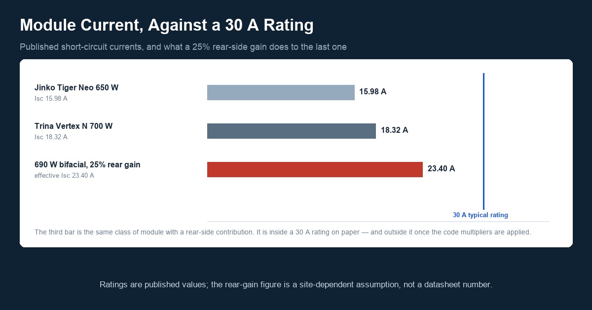
- Trina Vertex N 700 W (TSM-NEG21C.20-700): Isc 18.32 A, Impp 17.29 A, maximum series fuse rating 35 A.
- Jinko Tiger Neo 650 W (JKM650N-66QL6-BDX): Isc 15.98 A.
- A 690 W bifacial module with 25% rear-side gain: effective Isc 23.40 A.
Two things are worth separating immediately. The maximum series fuse rating (35 A in the first example) is not a current the connector carries; it is the largest overcurrent device permitted in series with the module string, and it exists to protect the module's internal ribbons and bypass diodes against reverse current. The number that matters for the connector is Isc, and for a bifacial module it is the effective Isc after rear-side contribution.
2. Bifacial: the datasheet value is a floor, not a ceiling
A bifacial module is rated at front-side standard test conditions. In the field it also collects light on the rear face, and the rear contribution depends on albedo, ground cover, mounting height, row pitch and tracker geometry. Published rear-side gains range widely; 10% over dark gravel is one thing, 25% or more over white single-ply membrane or snow is another.
The consequence for connector sizing is direct. Take the 690 W example: a front-side Isc of roughly 18.7 A becomes 23.40 A at 25% rear gain. That 23.40 A is the number that has to go through every connector in the string, and it is about 28% higher than the number on the datasheet.
Bifacial current measurement is itself standardised — IEC TS 63202-3 covers the measurement of current-voltage characteristics of bifacial cells and modules — but the designer still has to choose a rear-gain assumption for the site. If the assumption is conservative the string is safe and the array is slightly over-built; if it is optimistic, the connectors are the first component to find out.
3. What the code does with Isc
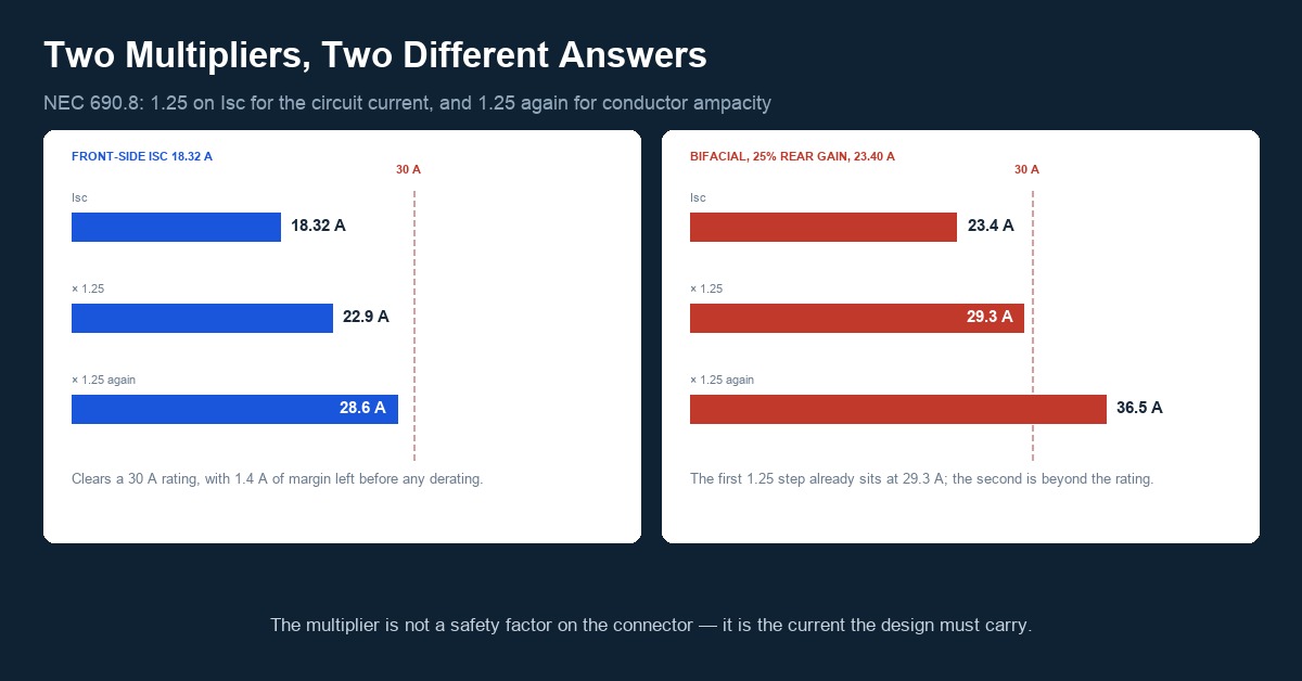
Under NEC 690.8(A)(1), the maximum source-circuit current is the sum of the parallel-connected module short-circuit currents multiplied by 1.25. Conductor sizing then applies a second 1.25 for continuous duty, which is where the familiar 1.56 factor comes from. Running the numbers for a single string of 700 W modules:
- Isc = 18.32 A
- Maximum circuit current (1.25 × Isc) = 22.9 A
- Conductor ampacity requirement (1.25 × 1.25 × Isc) = 28.6 A
And for the bifacial case at 23.40 A effective Isc:
- Maximum circuit current = 29.3 A
- Conductor ampacity requirement = 36.5 A
The second pair of numbers is the interesting one. A connector rated 30 A — the figure most commonly quoted for MC4-class products — is now essentially at its limit on the first multiplier, and below the second. That does not mean a 30 A connector is illegal here; it means the margin that used to exist has been consumed by module evolution, and there is no headroom left for high ambient temperature, bundling or a slightly imperfect crimp.
4. Where a "30 A rating" actually comes from
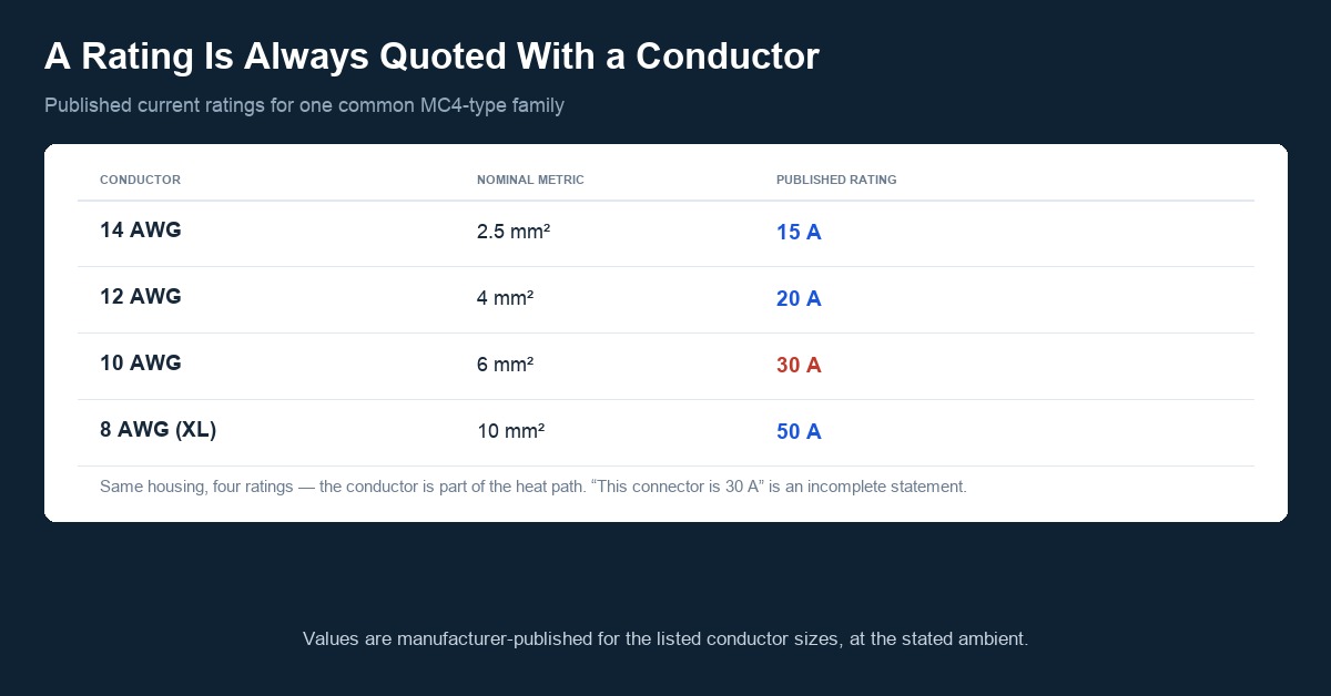
A connector current rating is not a single number stamped on a housing. It is a rating established for a specific combination of conductor cross-section, cable type and ambient temperature, and it is meaningless without all three. Published values for one widely used family make the dependency obvious: 15 A with 14 AWG, 20 A with 12 AWG, 30 A with 10 AWG, and 50 A with 8 AWG on the extended-range variant.
Read that way, "this connector is 30 A" is an incomplete statement. The honest version is "30 A with 6 mm² conductor, at a stated ambient, with the manufacturer's specified tooling." The same housing with a smaller conductor carries less, because the conductor is part of the heat path: a crimp joint sheds heat through the cable as well as through the housing.
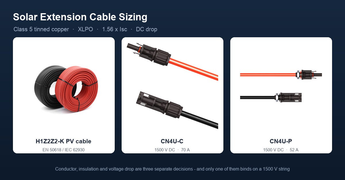
That is why the ampacity conversation and the cable-sizing conversation cannot be separated. Our PV DC cable sizing guide covers the conductor side of the same calculation, including voltage drop over long runs.
5. The square law, applied to a contact
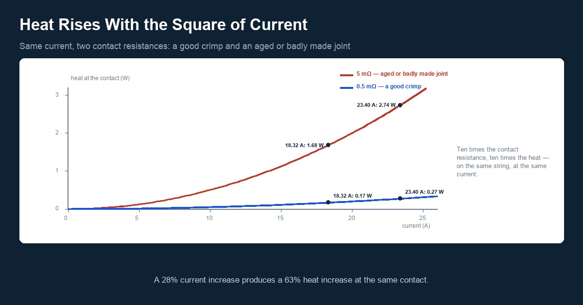
Heat generated at a contact is I²R, so the penalty for higher current is not linear. Using a contact resistance of 0.5 mΩ, which is a reasonable figure for a well-made crimp:
- At 18.32 A: 18.32² × 0.0005 = 0.17 W
- At 23.40 A: 23.40² × 0.0005 = 0.27 W
A 28% increase in current produces a 63% increase in heat at the same contact. Now take a joint that has aged or was poorly crimped, at 5 mΩ:
- At 18.32 A: 1.68 W
- At 23.40 A: 2.74 W
Two watts dissipated inside a plastic shell the size of a thumb is enough to drive the contact well above the housing's continuous operating temperature. This is the mechanism behind the temperature-rise requirement in IEC 62852: the standard limits the temperature rise at rated current, and a connector that is within its rating with a good crimp can exceed it with a marginal one.
6. How the temperature-rise allowance gets spent
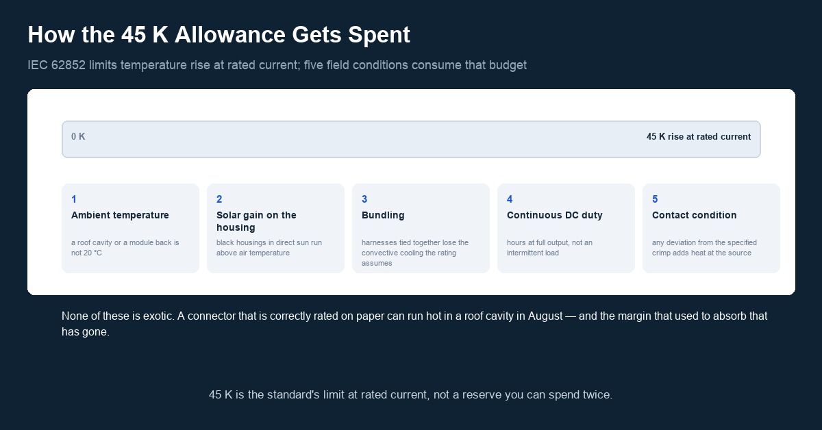
IEC 62852 limits temperature rise at rated current to 45 K. Combined with a rated ambient of 85 °C for many connectors, the contact is already designed to operate somewhere around 130 °C at full rating. What consumes that allowance in practice:
- Ambient temperature. A connector in a roof cavity or behind a module on a 40 °C day starts well above the 20 °C laboratory condition.
- Solar gain on the housing. Black housings in direct sun sit above air temperature.
- Bundling. Harnesses tied tightly together, or connectors tucked into trunking, lose the convective cooling the rating assumes.
- Continuous duty. A DC string delivers for hours, not intermittently.
- Contact condition. Any deviation from the specified crimp, or a mismated pair, adds resistance at exactly the point where the heat is generated.
None of these is exotic. A connector that is correctly rated on paper can run hot in a roof cavity in August, and the margin that used to absorb that has gone.
7. When to step up
Practical thresholds, working from the arithmetic above:
- Effective Isc above roughly 15 A — check whether the connector's rating for the conductor size in use still clears the first multiplier with margin, not just with equality.
- Effective Isc above roughly 20 A — move to 6 mm² conductor and the corresponding connector rating; 4 mm² is now doing the job on voltage drop as well as on current.
- Effective Isc above roughly 25 A, or any high-ambient / bundled installation — 10 mm² conductor with a connector rated for it, and a rated current that leaves headroom after the continuous-duty multiplier.
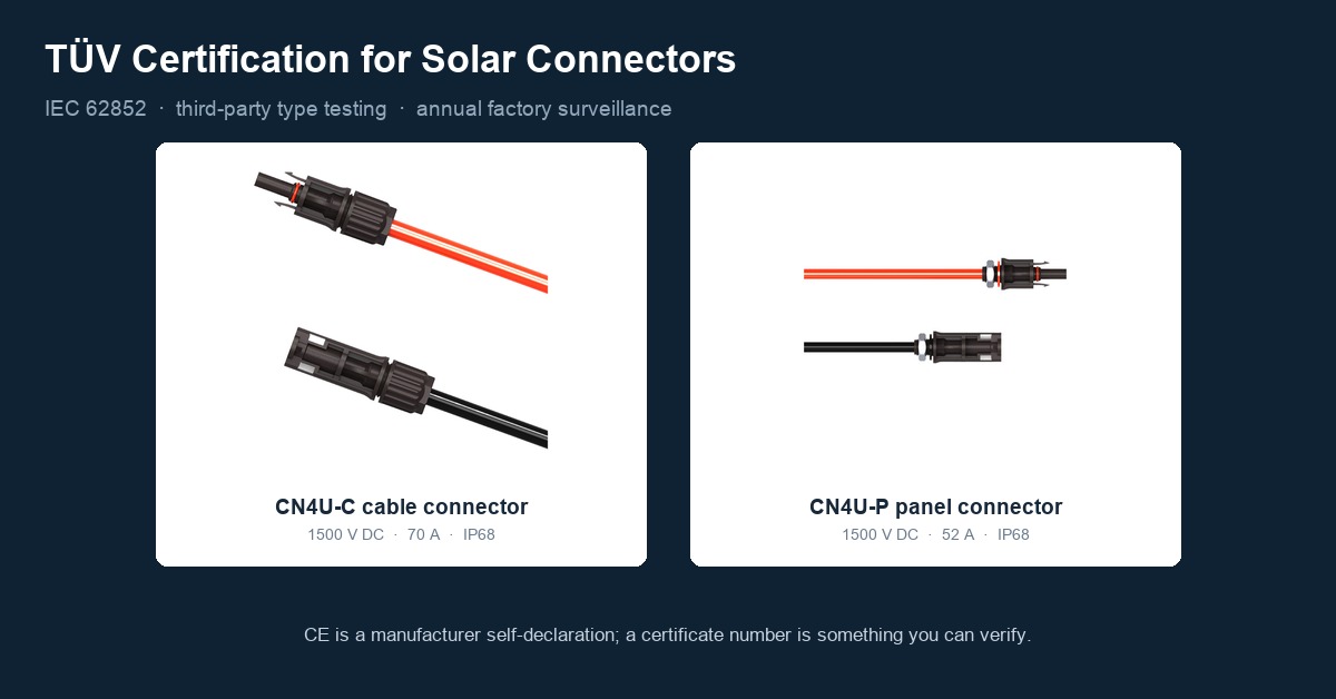
Where the design calls for genuine headroom rather than a marginal pass, the connector rating has to be specified the same way it is measured: at a stated conductor size and ambient. The CN4U-C cable connector is rated 70 A max and the CN4U-P panel connector 52 A max; both figures are quoted with their conductor range and temperature rating on the product page, and they are the values a designer should compare against the calculated continuous current rather than against Isc alone.
Voltage class matters alongside current. A higher-current design is usually a 1,500 V design, and the qualification boundaries are different at each voltage level — see 1500V vs 1000V PV Connectors.
8. What to check on site
The calculation is only as good as the installation. Three checks catch most of the gap between the design number and the installed one:
- Confirm the effective Isc used in the design, including the rear-gain assumption and the record-temperature open-circuit voltage correction.
- Confirm the connector rating for the conductor actually installed, not for the largest conductor the housing accepts.
- Confirm the crimp was made with the specified die and verified. Contact resistance is the variable that turns an adequate rating into an inadequate one, and it is also the easiest variable to control — see the crimping tool guide.
Frequently asked questions
Is a 30 A connector still enough for a 700 W module?
It depends on the conductor it is rated with and on the effective short-circuit current, not on the module wattage alone. A 700 W module with Isc 18.32 A gives a maximum circuit current of 22.9 A under NEC 690.8(A)(1) and a conductor ampacity requirement of 28.6 A. If the same module is bifacial and the site produces 25% rear gain, effective Isc reaches about 23.4 A, and the two numbers become 29.3 A and 36.5 A — beyond a 30 A rating.
What is the "maximum series fuse rating" on a module datasheet?
It is the largest overcurrent device permitted in series with the string, typically 35 A on current high-power modules. It is a protection limit for the module's internal conductors and bypass diodes, not a current the connector carries under normal operation. Sizing the connector from that number instead of from Isc is a common error.
Why does the connector rating change with cable size?
Because the conductor is part of the thermal path. A crimp joint sheds heat through the cable as well as through the housing, so the same connector body is rated lower with a smaller conductor. Published ratings for one common family run 15 A with 14 AWG, 20 A with 12 AWG, 30 A with 10 AWG and 50 A with 8 AWG on the extended-range variant — the rating is meaningless without the conductor size attached.
How much margin is enough?
Enough that the rating still clears the continuous-duty current after high ambient temperature, solar gain on the housing and bundling are accounted for. A design that only just clears the first multiplier with a nominal rating has no allowance left for a crimp that is slightly out of specification, which is the most common field deviation.
Does higher current mean I should increase cable size too?
Usually yes. At the current levels of modern high-power modules, 4 mm² is frequently limited by voltage drop over the run length before it is limited by ampacity, so moving to 6 mm² or 10 mm² is often driven by the drop calculation rather than by thermal limits alone.
References
- Trina Solar Vertex N module datasheet, TSM-NEG21C.20-700: Isc 18.32 A, Impp 17.29 A, maximum series fuse rating 35 A
- Jinko Solar Tiger Neo datasheet, JKM650N-66QL6-BDX: Isc 15.98 A
- NFPA 70 (NEC) 690.8(A)(1) and 690.8(B): maximum circuit current and conductor ampacity multipliers
- IEC 62852, Connectors for DC-application in photovoltaic systems — Safety requirements and tests (temperature-rise limit and rated current conditions)
- Amphenol UTX series published ratings: 15 A (14 AWG), 20 A (12 AWG), 30 A (10 AWG), 50 A (8 AWG, UTX-XL)
- IEC TS 63202-3, Measurement of current-voltage characteristics of bifacial photovoltaic cells and modules
- Treasol, PV DC Cable Sizing: 4mm² vs 6mm² vs 10mm²
- Treasol, 1500V vs 1000V PV Connectors
Reviewed by the Treasun New Energy technical team. Ratings quoted are manufacturer published values; always confirm against the current datasheet for the exact part number and conductor size.