
Pre-assembled PV cable assemblies with MC4 compatible connectors, TUV cable and IP68 joints. Built to your array drawings, tested before shipment.
Every assembly below is built to a drawing: conductors cut to length, MC4 compatible connectors terminated on the bench, branch joints overmolded, each leg labelled and tested before packing. Ratings shown are the connector-body values. The trunk of a trunk-and-drop set is sized to the summed current of its drops, not to a single string.
A solar wire harness replaces the cutting, stripping and crimping that would otherwise happen on the roof or out in the field. Treasol builds these assemblies against a project drawing: conductors cut to length, MC4 compatible connectors terminated on the bench, branch joints overmolded, and every leg labelled before the set goes into a box. What arrives on site is a wiring set that already follows the array layout, not a drum of cable and a bag of loose housings.
This page covers the topologies that suit different array shapes, the ratings that govern a 1500 V DC build, the cable and connector options, the five steps to specify a harness, and the tests each unit clears before shipment.
A solar wire harness is a factory-assembled wiring unit. Conductor lengths, branch positions, connector types, bundling and labels are all fixed before production starts. The installer receives a set that maps to the array: this leg goes to string 4, that leg to string 5, the trunk runs along the purlin to the combiner.
Standard PV cable is a different product. It arrives as one continuous length on a drum. Someone on site cuts it, strips the insulation, crimps the terminals and snaps the housings together. Each of those steps adds a failure mode — a crimp pulled short of the die, a seal left proud of its seat, a polarity reversed because the red and black runs were cut in the wrong order.
A harness moves that work to a bench where crimp height is set by a calibrated tool, seals are checked against a gauge, and every finished leg is tested under load before it is packed. The trade-off is lead time and the need to supply drawings early. What comes back is consistency that field assembly does not produce at volume.
The difference matters most on large arrays. A rooftop with 40 strings and 80 field-made joints has 80 places for a fault to appear months later. The same array wired with harnesses has those joints made under inspection, with a test record attached to each one.
Three topologies cover most array shapes. The choice depends on how strings are grouped and how far they sit from the combiner.
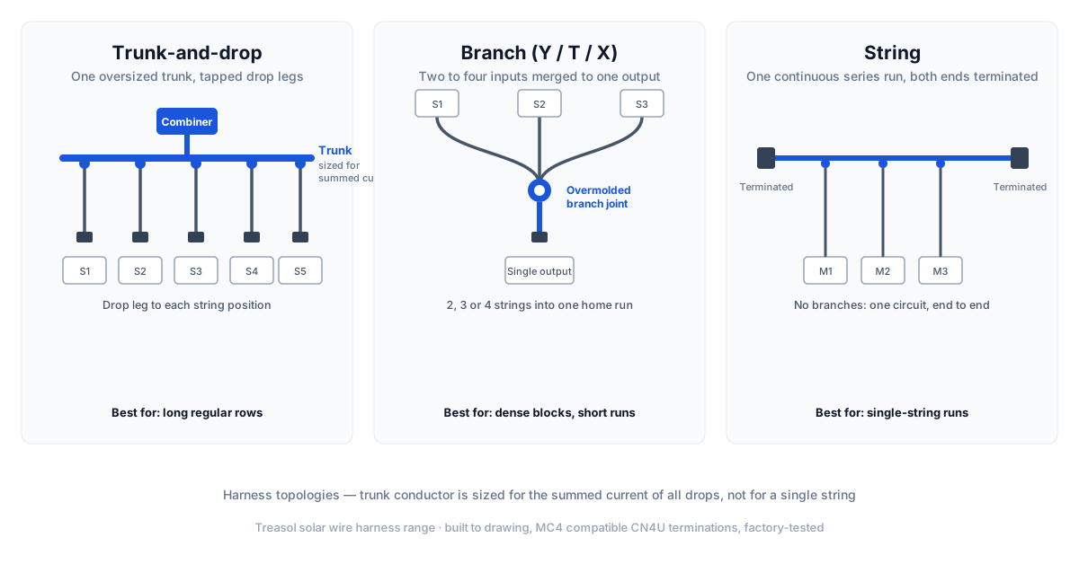
Trunk-and-drop. One large conductor runs the length of the array. Smaller drop cables tap off it at each string position, usually through an overmolded T joint. The trunk carries the summed current of every drop feeding it, so it is sized one or two steps above the drops. This suits long, regular rows where strings repeat at fixed intervals.
Branch (Y, T and X). Two or more inputs merge into one output. A Y branch combines two strings, a T branch taps one, and an X branch handles three or four. Branch harnesses are used where strings are short and the array is dense, or where modules are grouped in blocks rather than rows.
String harness. A single series run, terminated at both ends, with no branches. Used where the string is wired as one continuous circuit from the first module to the last, or as the building block inside a larger trunk-and-drop design.
The full range is listed under wiring harness products.
The trunk conductor in a trunk-and-drop design is where most sizing errors happen. It does not carry one string current; it carries the sum of every drop behind it. A harness with six 10 A drops feeding a trunk needs a trunk rated for 60 A, not 10 A.
Harness ratings are set by the weakest component in the assembly — the connector, the overmold, or the cable. Treasol harnesses are built around connector bodies rated to the values below.
Conductor sizing follows the current the leg carries and the voltage drop over its actual length.
Single core in free air, 90 °C conductor in a 60 °C ambient. Ratings differ between cable makers and installation methods. Derate for bundling, conduit, direct roof contact and high ambient temperature, then confirm against the standard your project is built to.
Voltage drop is the constraint that usually decides the size, not the current rating. A 4 mm² drop may carry 20 A comfortably but still lose too much voltage over a 40 m run. The check is: multiply the string current by the conductor's resistance per metre, multiply the result by the round-trip length, and compare it against the array voltage. Most projects hold total DC drop between the module and the inverter to 1–2%.
Cable. Treasol harnesses use H1Z2Z2-K cable to EN 50618, with PV1-F to TÜV 2 PfG 1169 available where a project specifies it. The conductor is tinned copper, class 5 to EN 60228, which stays flexible at low temperatures and resists corrosion at the termination. Insulation and sheath are cross-linked halogen-free polyolefin, so the cable produces low smoke in a fire and holds up against UV and ozone over a long outdoor service life. Service temperature runs from −40 °C to +90 °C, with a conductor rating of +120 °C over 20,000 hours. Standard cross sections are 2.5, 4.0, 6.0, 10 and 16 mm² in red and black.
Connectors. Harnesses are terminated with CN4U-C cable connectors and CN4U-P panel connectors. Both are MC4 compatible with a Ø4 mm pin, rated 1500 V DC by TÜV and UL, tested at 12 kV, and IP68 when mated. Contact resistance sits below 0.5 mΩ. The CN4U-C terminates 14/12/10/8/6 AWG, covering 2.5 mm² through 16 mm². The CN4U-P is rated 52 A and covers 2.5, 4.0 and 6.0 mm², which is the range most panel-side connections fall into.
Pin plating is tin over copper. Tin holds a stable contact resistance across the temperature cycle and does not form the insulating oxide layer that bare copper does after years in a humid enclosure.
Five steps, in order. Skipping the second one is the most common source of undersized trunks.
Step 1 — Fix the array layout. Module positions, string grouping, and where the combiner or inverter sits. The harness is built to this drawing, so changes after release mean new parts.
Step 2 — Establish the string current. Take it from the module short-circuit current with the safety factor your standard requires, not from the nominal operating current. A string with an Isc of 11 A and a 1.25 factor is designed for about 14 A.
Step 3 — Size conductors for current and drop. Pick the cross section from the current rating table, then check voltage drop over the real run length. Where a drop fails the drop check, move up one size rather than shortening the route.
Step 4 — Size the trunk for summed current. Add the currents of every drop feeding the trunk. A harness with eight 14 A drops needs a trunk rated for 112 A, which puts it well above the standard 10 mm² leg and into a bus or parallel-run design.
Step 5 — Choose connectors and labelling. CN4U-C for cable-to-cable, CN4U-P for panel-side. Then the labels: printed text, barcode, or both, applied at each leg so the installer can identify string 7 without tracing it back.
Supply the drawings as early as possible. The two things that delay harness orders are an unfinalised array layout and a combiner position that moves after the cable schedule is written.
These are the figures buyers ask for first. They are typical values for a mid-volume PV harness line and are confirmed against the drawing at quotation.
Capacity is held across several parallel lines, so a repeat order does not normally queue behind new projects. Where a project has a fixed energisation date, say so at enquiry stage and the schedule is planned backwards from it.
Eight items cover most orders. The first four are enough for us to come back with a design.
Already have the layout? Send the string grouping and cable schedule and we will come back with conductor sizes, connector types and a production schedule.
Get a harness design review →Rooftop. Access is the constraint. Crews work at height, often on sloped surfaces, and every minute spent stripping cable is a minute on a ladder or a walk board. Harnesses cut that time because the termination work is done. The second issue is heat: cable lying on a dark roof surface in summer runs hotter than the same cable in free air, so the derating in section 3 is not optional. Routes should stay clear of standing water and off the hot membrane where possible.
Ground-mount. Distance is the constraint. Runs from the far end of a tracker row to the combiner can reach 60 m or more, which makes voltage drop the governing check. Trunk-and-drop topology suits this shape well — the trunk runs the row and drops tap at each string. Buried sections need cable rated for direct burial or a conduit, and the routing plan has to account for the trenching sequence.
Tracker. Movement is the constraint. Harness sections near the pivot and along the torque tube flex with every rotation, so those runs need strain relief at fixed points and slack loops where the cable crosses a moving joint. Cable rated for repeated bending and a protective sleeve at wear points are standard practice. A harness built for a fixed-tilt array will not survive on a single-axis tracker without those additions.
Routing, clipping intervals and strain relief on site are covered in the harness installation best practices guide.
The comparison is not only about labour hours. It is also about what can be inspected.
Field wiring still has a place: repairs, short runs, and arrays where the layout changes during installation. For a fixed design built across many identical blocks, the factory route produces fewer call-backs.
The measurable gain is in how many terminations a crew makes on site. A harness removes most of them. Crimping is the step with the highest defect rate in PV field work, and it is the step a harness eliminates.
The table below lists every wiring harness in the Treasol range with the ratings that govern the choice: topology, current, voltage and conductor. Current ratings are per configuration — a trunk built with eight drops is sized for the summed current, not for one string.
Ratings are the connector- and cable-body values from the product data sheets. Final conductor size is set by the string current and the voltage drop over the actual run length, per section 5.
Every harness is inspected before it ships. The checks are:
Continuity and polarity. Each leg is tested end to end, and contact resistance is held below 0.5 mΩ per mated pair. Polarity is confirmed, not assumed, so a reversed drop is caught on the bench rather than at commissioning.
Insulation resistance. Measured at 1000 V or 1500 V DC depending on the system voltage the harness is built for, with an acceptance threshold of 100 MΩ and above. Readings are recorded per unit.
Pull force. Each terminated connector is pull-tested to the value the crimp specification sets for that conductor size — 4 mm² terminations are pulled to 150 N and 6 mm² to 200 N, with the result logged per termination. A crimp that pulls out in service leaves an open circuit or, worse, a high-resistance joint that heats.
Visual and dimensional. Overmold integrity, seal seating, label legibility, and conductor length against the drawing.
Units are digitally marked so a test record can be traced back to a specific harness. Where a project requires it, test reports are supplied with the shipment.
Harness components are certified to TÜV Rheinland, UL, CE and RoHS. Cable is to EN 50618 (H1Z2Z2-K) or TÜV 2 PfG 1169 (PV1-F). Connectors are assessed to IEC 62852 and UL 6703, the two standards that govern PV connector construction and testing.
The design life target is 25 years of outdoor service, which is why the insulation is cross-linked rather than thermoplastic and why the contacts are tinned. Both choices are driven by what degrades first: insulation that embrittles under UV, and contacts whose resistance climbs as the surface oxidises.
Safety class II and UL 94-V0 flame rating apply across the connector range. IP68 applies in the mated state — an unmated connector is not IP68, which is why harnesses ship with sealing caps on any open ends.
Crimp tooling is calibrated on a set interval and crimp height is checked at the start of each run, not only at the end of it. A worn die is caught by that check, not by the pull test at the end of the line.
A standard PV cable is a single continuous length of cable. A solar wire harness is a factory-assembled unit that combines multiple cables, pre-terminated MC4 compatible connectors, overmolded branch joints and custom labelling into one assembly matched to a specific array layout.
Yes. Harnesses are built with PV-rated insulation and creepage distances suitable for 1000 V and 1500 V DC system designs, using TÜV and UL certified cable, terminals and seals. The UL rating also covers 600 V DC for projects built to that level.
Standard sizes are 2.5 mm², 4.0 mm², 6.0 mm² and 10 mm², corresponding to 14, 12, 10 and 8 AWG. The 16 mm² size is available where the connector termination supports it. Trunk conductors are sized up relative to the drops because they carry the combined current of several strings.
Yes. Harnesses are terminated with Treasol CN4U-C cable connectors and CN4U-P panel connectors. Both are MC4 compatible, rated 1500 V DC by TÜV and UL, tested at 12 kV, and IP68 in the mated state, with contact resistance below 0.5 mΩ.
Start from the string short-circuit current with the safety factor your standard requires. Size the conductor for that current, then check voltage drop over the actual run length rather than assuming the current rating alone is enough. The trunk carries the summed current of all drops feeding it, so it is normally one or two sizes larger than the individual drop cables.
Yes. Harnesses are built to project drawings with specified conductor lengths, branch positions, connector types, bundling and printed or barcode labelling for each string. Supplying the array layout and cable schedule early is what keeps the schedule short.
Every harness is inspected and digitally marked. Tests include continuity and polarity verification, insulation resistance at 1000 V or 1500 V DC, and pull-force validation on each terminated connector. Test reports can be supplied with the shipment where a project requires them.
Samples are produced in 5-7 working days for a repeat configuration and in 7-12 working days for a new drawing. Production runs 15-20 days after drawing release for a repeat configuration, and 20-30 days after sample approval where the design is new or needs overmold tooling. Freight and any inspection the customer carries out add to the door-to-door time. A confirmed schedule is issued with the quotation, not after it.
A repeat configuration starts at 200 sets per model. A new drawing starts at 500 sets per model, because tooling, cable scheduling and test fixture setup are fixed costs that have to be spread across the run. Sample orders of 1-5 sets are built before the production run and credited against it. Monthly capacity is 60,000 sets and above, so a repeat order does not normally queue behind new projects.
Price is built from five things: conductor length and cross section, connector count and type, branch joint construction, labelling, and the test and documentation the project requires. Two harnesses with the same number of connectors can differ in price because one is built in 4 mm² and the other in 10 mm². Quotes are issued against a drawing or cable schedule rather than from a unit price list.
Yes. Prototypes or sample harnesses are produced first so the fit, connector mating and labelling can be checked against the panel frame or on site before the production run starts. This is standard on custom orders and it is what catches a branch position that sits a few centimetres off the purlin.
Component certification — TÜV Rheinland, UL, CE and RoHS, with cable to EN 50618 (H1Z2Z2-K) or TÜV 2 PfG 1169 (PV1-F) and connectors assessed to IEC 62852 and UL 6703 — covers the range. Test records from the pre-shipment inspection can be supplied with the shipment where the project requires them. Ask for this when the order is placed so the paperwork is prepared with the goods.
Yes. CN4U-C cable connectors and CN4U-P panel connectors use the MC4 mating geometry with a Ø4 mm pin and mate with the original MC4 connector. They are MC4 compatible products made by Treasol, not Staubli originals — MC4 is a Staubli trademark. Where a project specifies the original manufacturer's part, that needs to be stated at specification stage.
Warranty covers defects in materials and workmanship over the period stated in the order confirmation. Because a harness is built to a specific drawing, the warranty covers the assembly as specified: damage arising from installation, routing that departs from the agreed design, or mating with connectors outside the MC4 geometry is not covered. Confirm the term that applies when the order is quoted.
Share the layout, string grouping and cable schedule. We will come back with a harness design, conductor sizes and a production schedule.
Request a Harness QuoteFaster than a form: send the drawing or a photo of the existing harness on WhatsApp and we will reply with a design and a schedule. Samples are produced before the production run.


