
PV Connector Cross-Mating: What Makes Two Connectors Safe to Mate
Two connectors can both be rated 1500 V DC, both be certified to IEC 62852, and both come from factories with proper quality control. None of that answers the only question that matters at the joint: has this particular pair been evaluated as a mating combination?
Applies to PV DC connectors, fuse connectors, diode connectors and branch connectors. MC4 is a registered trademark of Stäubli International AG. Treasol is an independent manufacturer and is not affiliated with or endorsed by Stäubli.
The short answer
Compatibility is a property of the mated joint, not of either connector. The features that decide it — contact geometry, spring pressure, sealing and locking — are internal and are defined by each manufacturer for its own product family.
- Match the exact model, not the label
- Check the applicable installation standard
- Ask the supplier for a written statement
Standards are cited for orientation only. Always confirm the edition in force in the relevant jurisdiction and the edition named in the project specification.
In one paragraph
A PV connector's voltage rating or IEC certification does not automatically prove compatibility with every connector from another manufacturer. A connector never works alone: current is carried by a male and a female contact pressed together, held by a locking mechanism, sealed against weather and crimped onto a cable. Compatibility is a property of that whole assembly. Cross-mating should therefore only be considered when the exact combination has been approved under the applicable certification and project requirements — and the standards that govern the mating decision should be read in the edition in force where the array is installed.
What cross-mating actually means
Cross-mating is joining a male and a female connector that were not designed and qualified as a pair by one manufacturer.
The features that decide the outcome are internal
Contact geometry, dimensional tolerances, contact material and plating, spring pressure, crimp design, housing and insulation dimensions, sealing structure, locking mechanism, accepted cable range, temperature behaviour and environmental resistance. Each of these is defined by a manufacturer for its own product family. Nothing in the datasheet of Connector A describes how its spring force will behave against the contact geometry of Connector B.
Physical fit proves very little
Two connectors from different manufacturers may fit together convincingly. They can click into place, lock, pass a continuity check, carry current during commissioning and look dimensionally similar.
None of that demonstrates long-term compatibility, because the mating interface — contact area, contact pressure and seal compression — is not visible from the outside.
Why a 1500 V rating does not settle the question
A 1500 V DC rating confirms that a connector has been designed and tested for that voltage under specified conditions. It says nothing about whether that connector is suitable for mating with every other 1500 V connector.
Two products can carry identical markings — DC 1500 V, 30 A, IEC 62852, TÜV, UL, IP68 — and still have mating interfaces that were never evaluated against each other. Electrical ratings and mating compatibility are related, but they are not the same claim.
This is the point at which many specification errors begin. A replacement connector is selected because the voltage and current match the original, and the fact that the replacement carries its own valid certificate is read as evidence that the substitution is acceptable. Certification of a part is not certification of a pair. The testing and qualification article covers what the type tests actually verify, and what they cannot.
The standards that govern mating
Product standards qualify a connector. Installation standards govern whether two connectors may be joined. These are different jobs.
| Standard | Scope | What it covers | What it does not cover |
|---|---|---|---|
| IEC 62852 | Product standard for PV DC connectors | Safety requirements and tests for connectors used in DC circuits of photovoltaic systems, for the voltage and current ranges defined by the standard. Tested on the connector as a product. | Any combination of that connector with a different manufacturer's connector. Certification does not extend to a pairing. |
| EN 50521 / EN 62852 | European designation | The European connector standard cited in Treasol's certification documentation. EN 50521 has been superseded by EN 62852, the European adoption of IEC 62852. | Nothing additional on mating. Where a project names a specific edition, that edition governs. |
| UL 6703 | North American product standard | Connectors for use in photovoltaic systems, recognized for the U.S. and Canada under the National Electrical Code, across the voltage classes it defines. | Cross-brand combinations, unless the listing itself identifies the specific intermateable pairing. |
| IEC 62548-1 (+ Amendment 1) |
Installation standard — PV array design | Design requirements for PV arrays. Earlier editions required plugs and socket connectors mated together in a PV system to be of the same type and from the same manufacturer. | It does not certify any connector; it constrains how connectors are selected and combined on site. Confirm the edition in force. |
| IEC 60364-7-712 | Installation standard — PV power supply systems | Requirements for low-voltage PV installations. The 2017 edition used the same same-type-same-manufacturer wording for mated connectors; newer editions have been issued. | Product performance. Edition and national adoption vary by jurisdiction. |
| NEC 690.33(C) | U.S. installation code | Requires mated PV connectors to be of the same type from the same manufacturer, or specifically listed and identified as intermateable. | It does not test anything on its own; the compliance evidence is the listing or intermateability documentation. |
| TÜV 2 PfG 2740 | TÜV Rheinland own specification | A TÜV Rheinland component specification applied to PV connectors. TÜV Rheinland also publishes technical guidance on the cross-connection of PV connectors. | Treasol cites this specification for orientation only and does not claim that it defines the applicable scope of any specific Treasol model. |
| IEC 63678 | Standard in development | Work towards a standardised plug and socket design for DC PV systems, in development since 2023. | Not yet published as a basis for design. No compatibility claim should rest on it today. |
The standards above are named for orientation. Standards are revised, and national adoption lags publication. The edition that governs a given project is the one in force in the relevant jurisdiction, together with any requirements written into the project specification. Treasol publishes a full index of connector, cable and installation standards in the PV connector and solar cable standards hub.
Cross-mating decision matrix
A starting point for the assessment, not a substitute for the project specification or the manufacturer's instructions.
| Situation | Physical fit | Ratings match | Pair certified | Verdict |
|---|---|---|---|---|
| Same brand, same series | Yes | Yes | Yes | Proceed |
| Same brand, different series | Check the datasheet | Check | No | Confirm with the maker first |
| Two different certified brands | Usually yes | Maybe | No | Avoid on new builds |
| Certified part with an unbranded copy | Often yes | Unknown | No | Do not use |
| 1500 V part in a 1000 V circuit | Yes | Over-rated | No | Acceptable, check the current rating |
| 1000 V part in a 1500 V circuit | Yes | Under-rated | No | Not allowed |
Where cross-mating becomes a risk
Five mechanisms explain why a joint that looks and feels correct can still be the wrong joint.
1. Contact geometry
The male and female contacts must maintain the intended contact area and pressure. Small differences in dimension or tolerance change the actual contact condition, even when the parts assemble without complaint.
2. Contact resistance
A marginal interface raises electrical resistance. Under continuous DC load, the heat generated at the joint follows P = I²R, where I is the current and R is the resistance of the connection. A small increase in resistance becomes significant when a connector carries current all day for decades. This is why a contact-resistance figure matters more than a maximum current on a datasheet: the acceptance criterion used in qualification is typically below 0.5 mΩ, measured by the four-wire method.
3. Sealing
PV connectors live outdoors and face rain, humidity, dust, UV radiation, temperature cycling, condensation and mechanical movement. The sealing system is designed around a specific housing and cable dimension. A connection that is mechanically acceptable has not necessarily preserved the intended degree of environmental protection, and an IP68 claim applies to the mated pair as designed.
4. Locking and mechanical retention
The locking structure is part of the design. A connection that feels secure may not provide the retention or the environmental performance of the intended mating pair, and retention is what keeps a joint stable through thermal cycling, wind loading and cable movement.
5. Manufacturing tolerances
Every manufacturer controls dimensions against its own design. When two independently designed systems are combined, the complete interface may not have been evaluated by either one. Nothing is necessarily out of tolerance in either part; the combination simply falls outside both declarations.
Can cross-mating cause arcing or overheating?
It can introduce a failure mechanism, particularly when the interface produces excessive contact resistance, insufficient contact pressure, poor mechanical retention or loss of sealing. It would be wrong to claim that every cross-mated connection will arc or burn.
The engineering concern is narrower and more useful: the combination may not deliver the validated performance of the intended mating pair, and there is usually no test evidence either way. That is a risk-management problem, and it is why published failure statistics are worth reading rather than dismissing.
DC PV circuits deserve particular attention because the array stays energised whenever there is sufficient sunlight. ABB's PV technical guidance notes, for example, that disconnecting PV connectors under load can trigger DC arcing and permanently damage the connectors. Selection, assembly, mating and maintenance should follow the applicable installation requirements and manufacturer instructions.
What published field data suggests
- European PV bankability work has attributed a substantial share of PV fires to connector and DC connection faults, with reported figures ranging widely by study.
- German incident data covering 1995–2012 associated connectors with roughly a quarter of the PV fires analysed.
- A 2024 NREL study of more than 50,000 operations and maintenance tickets across 837 U.S. sites reported long median downtimes, underlining how much availability a DC-side fault can cost.
These figures come from third-party research and are cited to show why the mating interface attracts attention. They are not Treasol findings, and they should be read with the scope and methodology of each study.
What “MC4 compatible” does and does not mean
Where the name comes from
MC4 stands for Multi-Contact, 4 mm — the original product family from Multi-Contact, now Stäubli. The 4 refers to the contact pin diameter. MC4 is a registered trademark, not an international connector standard.
Stäubli identifies MC4 as its Original MC4 product family and states that it does not recognise third-party products as compatible with that portfolio.
How the term is used in practice
A manufacturer may use it to describe the external interface or the intended application of a product. It cannot be read as “interchangeable with any MC4 connector”.
The exact connector type, manufacturer, model, certification, intended mating component, project requirements and module or inverter manufacturer requirements all still need to be verified. Our MC4 compatible connector page states the same position on its own products.
What counts as evidence of intermateability
Two connectors are intermateable when the specific combination has been evaluated and approved — not when they look the same.
| Evidence | Strength | What it actually establishes |
|---|---|---|
| Manufacturer statement naming the mating connector, with the supporting certificate or test report | Strongest | That a defined pair has been assessed against a named standard and edition. |
| Listing or certificate that identifies the intermateable pairing | Strong | That the specific combination appears in the scope of the listing — relevant to NEC 690.33(C) compliance. |
| A certificate for one connector only | Weak for pairing | That the product meets its own standard. Nothing about mating with a different brand. |
| Identical voltage and current ratings | Not evidence | Only that two products were designed for similar electrical conditions. |
| “They click together and the meter reads continuity” | Not evidence | That the housings are mechanically close. Nothing about contact pressure, seal integrity or long-term behaviour. |
If mixed connectors are already installed
Finding different connector brands on an existing array is not by itself proof that a connection has failed. It is a compliance and risk-assessment question, and it can be worked through in a defined sequence.
Identify the connector models
Record manufacturer and exact model number for the male connector, female connector, branch connector, inline fuse connector, inverter-side and module-side connectors. Photographs of the markings help.
Read the manufacturers' instructions
Review approved mating information from the connector, inverter and module manufacturers: approved mating connectors, connector family, compatible models, installation tools, crimping requirements, torque and cable sizes.
Check the project requirements
The specification may name specific brands or models. For commercial and utility-scale work this affects EPC acceptance, inspection, warranty, certification, insurance and O&M obligations.
Inspect the connections
Where it is safe to do so, look for discolouration, deformation, melting, cracks, damaged seals, loose locking mechanisms, signs of overheating, cable pull-out and incorrect crimping.
Consider thermal inspection
Thermal imaging under appropriate operating conditions can reveal abnormal temperature differences between joints. It is a diagnostic tool, not proof that an unapproved combination is compliant.
Rework where required
Where the combination does not meet project requirements or manufacturer instructions, replace or re-terminate using an approved mating pair. The method should be determined by the responsible electrical engineer together with the manufacturer's instructions.
Specifying and procuring to avoid the problem
The cheapest fix is at specification stage, where the decision costs nothing.
- One connector family per array, ideally per string. Where more than one brand will ever meet, the intermateability evidence has to exist before the first joint is closed, not after.
- Write the mating constraint into the technical specification. Name the connector family, and state that substitutions require documented intermateability under the applicable standard and edition.
- Do not accept equivalence by rating. A 1500 V / 30 A candidate is not an equivalent part merely because the numbers match.
- Specify the crimp. Contact resistance and pull-out strength depend on the die and cable combination, so name the cable sizes and require the die reference. Crimp quality is among the most common field faults and is entirely within the installer's control.
- Require the evidence with the goods. A certificate number that can be verified in the issuing body's public database is worth more than a compliance sentence in a brochure.
Questions to ask a supplier before ordering
| Question | Why it matters | What a good answer looks like |
|---|---|---|
| Which standard is the connector certified to? | “Tested to” is not “certified to” | IEC 62852 or UL 6703, with a certificate number |
| What are the voltage and current ratings? | They have to match the string, not just the part | 1500 V with the current rating and the test voltage |
| Do you state intermateability in writing? | A certificate covers a part, never a pair | A written statement naming the mating brand and the assessed standard |
| What is the contact resistance? | It is the main source of heat at the joint | Below 0.5 mΩ, measured by the four-wire method |
| Which cable sizes does the crimp cover? | Wrong dies are among the most common field faults | An explicit mm² and AWG range with the die reference |
| Can I have the certificate file? | Verification takes two minutes | A document with number, scope and validity |
Treasol's position on cross-mating
Treasol manufactures photovoltaic connectors, fuse connectors, diode connectors, branch connectors, junction boxes and PV wiring harnesses for solar applications. Our connectors are developed against defined applications and specifications rather than resting on the generic term “MC4 compatible”.
On mating, our published position is deliberately conservative and matches what the installation standards require: for product safety and compliance, Treasol male and female connectors should be used as matched pairs. We do not cross-mate connectors from different manufacturers, and we recommend the same to our customers, unless the exact combination has been approved under the applicable certification and project requirements.
Selection for a project should be based on the exact model, electrical ratings, certification, cable specification, mating configuration and installation requirements. Installers and EPC contractors confirming a large order are encouraged to verify the complete mating configuration first.
If you are replacing an existing connector, send us photographs of the connector, the manufacturer and model number, male and female connector details, cable size, system voltage, required current, application location, module or inverter model and the quantity required. Our engineering team can then assess which Treasol solution fits the available technical information.
Connector families designed to be used as matched pairs
Model-specific ratings. Applicable certification and documentation are confirmed per model before quotation. Part of the full solar PV connector range.
Last updated: October 2026

CN4U-C Solar Cable Connector
| Current | 70 A |
| Voltage | 1500 V |
| Protection | IP68 |

CN4U-P Solar Panel Connector
| Current | 52 A |
| Voltage | 1500 V |
| Protection | IP68 |

Branch Connector Series-2
| Current | 60 A output |
| Voltage | 1500 V |
| Protection | IP68 |

Branch Connector Series-1
| Current | 45 A output |
| Voltage | 1000 V |
| Protection | IP67 |

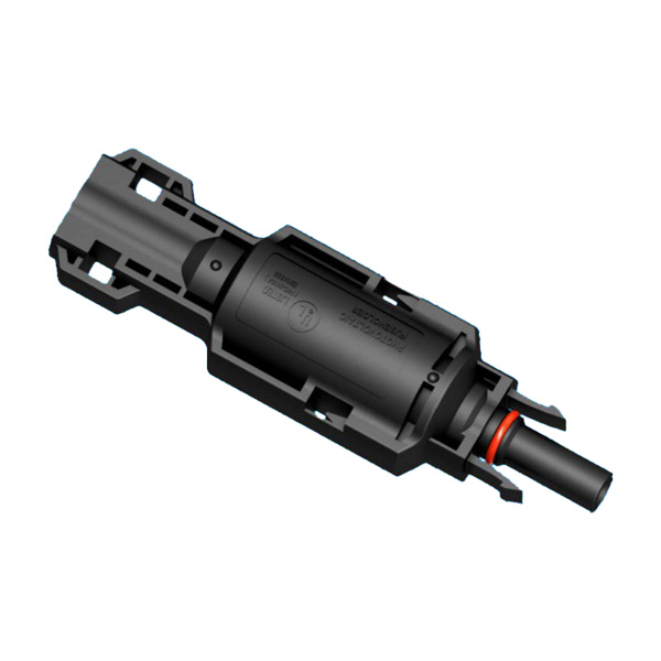
F4C-200-1085 Fuse Connector
| Current | 1–30 A |
| Voltage | 1500 V |
| Protection | IP68 |
D4A PV Diode Connector
| Current | 1–8 A |
| Voltage | 1000 V / 600 V |
| Protection | IP68 |

MC4 is a registered trademark of Stäubli International AG. Treasol is an independent manufacturer and is not affiliated with or endorsed by Stäubli. For product safety and compliance, Treasol male and female connectors should be used as matched pairs. Do not cross-mate connectors from different manufacturers unless the exact combination has been approved under the applicable certification and project requirements.
Certification & Compliance
Certification is product-specific. Scope varies by model and configuration, and applicable documents are confirmed before quotation.
TÜV Rheinland
PV connector certification to applicable IEC 62852 / EN 50521 requirements. Certificate numbers are provided on request and can be verified in the TÜV Rheinland public database.
UL Listed
UL 6703 certification for applicable photovoltaic connectors and junction boxes. Our solar fuse connector family is covered by UL file E364333, category Fuseholders, Photovoltaic.
CE Marking
Applicable European conformity requirements for relevant products. A Declaration of Conformity is available where the product falls within scope.
RoHS Compliant
Restriction of Hazardous Substances compliance documentation is available for applicable products.
Not every product model or configuration carries the same certification. Before ordering, confirm the exact product model, electrical rating, cable range, certificate number and applicable certification scope. See the standards and certification hub for how the standards map to each product family.
Frequently asked questions about cross-mating
The questions buyers, EPC contractors and O&M teams raise most often. More general questions are answered in our product FAQ.
Get a Matched-Pair Recommendation
Share your existing connector details, cable size, system voltage, current and the certification your project requires. We will reply with the recommended Treasol model, the applicable mating configuration, datasheet and certification information.
What to send for a compatibility review:
- Photographs of the existing connector and its markings
- Manufacturer and model number, male and female
- Cable size and conductor type
- System voltage and required current
- Module or inverter model
- The standard the project requires
Contact the PV connector team
Send us the information above and our engineering team will come back with the recommended Treasol model, the applicable configuration and the documentation your project requires. We normally respond within 24 hours.
Email: info@treasol.com
WhatsApp: +86 186 8861 9157
Contact us → Chat on WhatsApp