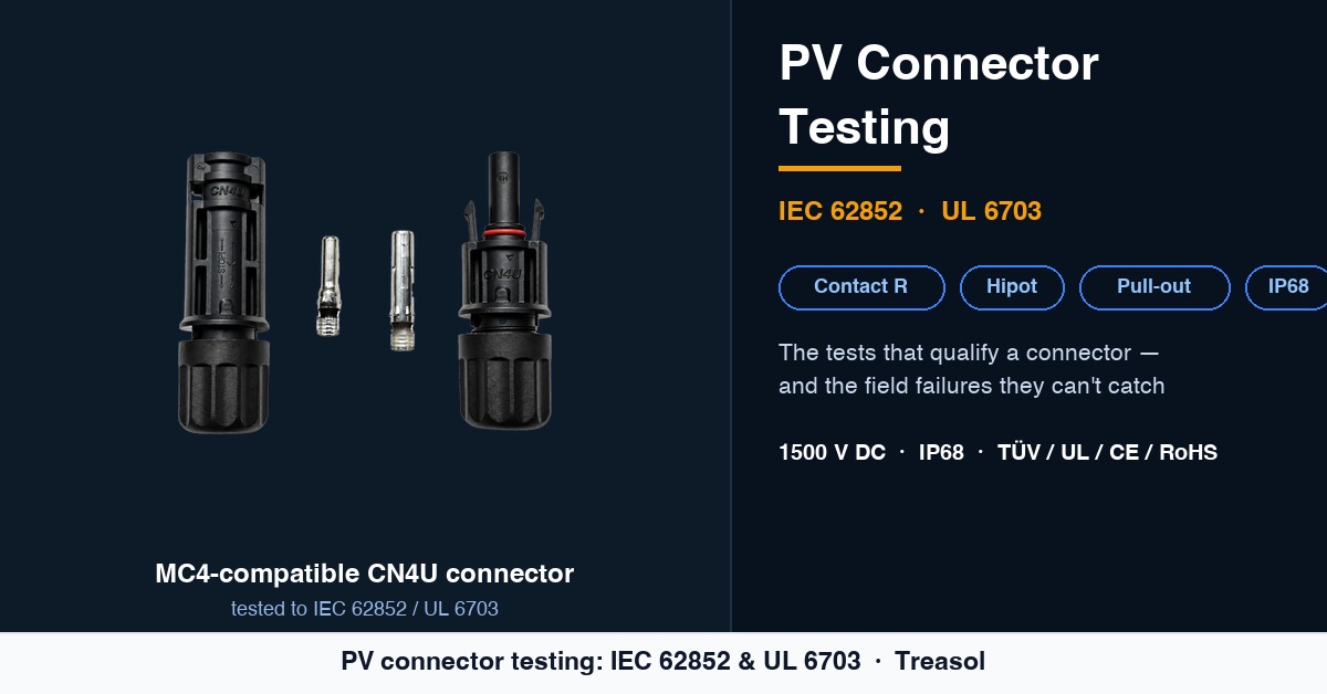
The standards referenced in this article are collected in our PV connector and cable standards reference.
A photovoltaic connector is the smallest line-replaceable component in a DC array, and one of the most failure-prone. Large-scale fire and reliability studies keep tracing rooftop arc faults and string outages back to a single mated pair. The difference between a 25-year install and a liability is knowing how a connector is qualified — and where that qualification stops.
The qualification tests for a PV connector live in IEC 62852, with UL 6703 as the North American counterpart. This is the test program, the acceptance criteria that separate a sound product from a box of look-alikes, and the field conditions a laboratory cannot reproduce.
1. The standard that governs qualification
PV DC connectors are not tested under generic electronics rules. They sit outdoors for 25-plus years, carry string current at 1000–1500 V DC, and have to hold up against heat, UV, salt, ammonia and mechanical abuse.
- IEC 62852:2014 — Connectors for DC-application in photovoltaic systems — Safety requirements and tests. The global reference for PV connector type testing.
- UL 6703 — the North American equivalent, recognized for the U.S. and Canada under the National Electrical Code.
- TÜV 2 PfG 2740 / 2 PfG 1169 — TÜV Rheinland component specifications often cited alongside IEC 62852 for the European market.
- IEC 62930 / EN 50618 (H1Z2Z2-K) and IEC 60228 — the cable and conductor standards a connector is paired with.
A "CE" or "TÜV" sticker alone proves nothing. The document that matters is the test report issued against IEC 62852 / UL 6703 by an accredited laboratory.
2. The test taxonomy
IEC 62852 groups qualification into four families: electrical, mechanical, environmental and flammability. Each row below maps a test to what "passing" actually means in service.
| Test | Basis | What "pass" means in practice |
|---|---|---|
| Contact resistance | IEC 62852 | Measured by the 4-wire (Kelvin) method; a typical new-state value sits below 0.5 mΩ — well into sub-milliohm territory. The value must hold through durability cycling, not just at hour zero. |
| Insulation resistance | IEC 62852 | ≥ 100 MΩ at 500 V DC between live parts and housing, in dry and damp conditions. |
| Dielectric withstand (hipot) | IEC 62852 | Withstands 2 × system voltage + 1000 V AC for one minute with no breakdown or flashover — roughly 4000 V AC for a 1500 V DC system. |
| Insertion / extraction force | IEC 62852 | Within a band that guarantees a secure lock and hand-mateability (commonly ~20–80 N), re-verified after mating cycles. |
| Durability (mating cycles) | IEC 62852 | Keeps electrical and mechanical performance through a defined number of connect/disconnect cycles, with contact resistance re-checked afterward. |
| Cable retention / pull-out | IEC 62852 | Axial pull (≥ 100 N; many specs call for 200 N) for one minute, with no disconnection and no more than ~20% change in contact resistance. |
| Vibration | IEC 60068-2 | Random and sinusoidal vibration simulating transport and tracker movement; no loosening, no performance shift. |
| Mechanical shock | IEC 60068-2 | Half-sine / square-wave pulses; structural integrity maintained. |
| Thermal shock | IEC 62852 | Rapid temperature transitions; sealing and function preserved. |
| Damp heat | IEC 60068-2 | 85 °C / 85 % RH for roughly 1000 h; insulation resistance must not collapse. |
| High-temperature endurance | IEC 62852 | Prolonged exposure at rated temperature; terminals and insulator unchanged. |
| Salt mist | IEC 60068-2-52 | Coastal and floating-array corrosion resistance; contact resistance drift within limits. |
| Mixed-gas corrosion | IEC 60068-2-43 / -60 | SO₂, H₂S and similar atmospheres — critical for industrial and petrochemical sites. |
| Ammonia resistance | IEC 62716 | Required for agrivoltaics and fishery-PV. |
| Ingress protection | IEC 60529 | IP68 = dust-tight and protected against continuous immersion beyond 1 m. IP67 (temporary immersion) is the lower bar. |
| Flammability / glow-wire | IEC 60695-2-11 | Non-metallic housing survives an 850 °C glow-wire without ignition; UL 94 V-0 is the common target. |
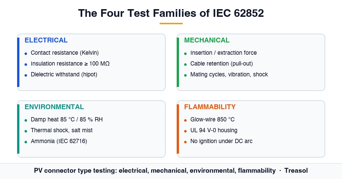
Two tests worth calling out, because a connector that passes hipot but pulls off the cable — or that ignites under a DC arc — is a non-starter: cable retention and flammability.
3. Reading a contact-resistance claim
"Contact resistance < 5 mΩ" (or a smaller figure) is advertised often. Treat it as a vendor specification, not a standard limit. IEC 62852 does not mandate a single magic number; it mandates stability — the joint must not drift out of tolerance through mating cycles, thermal cycling and corrosion.
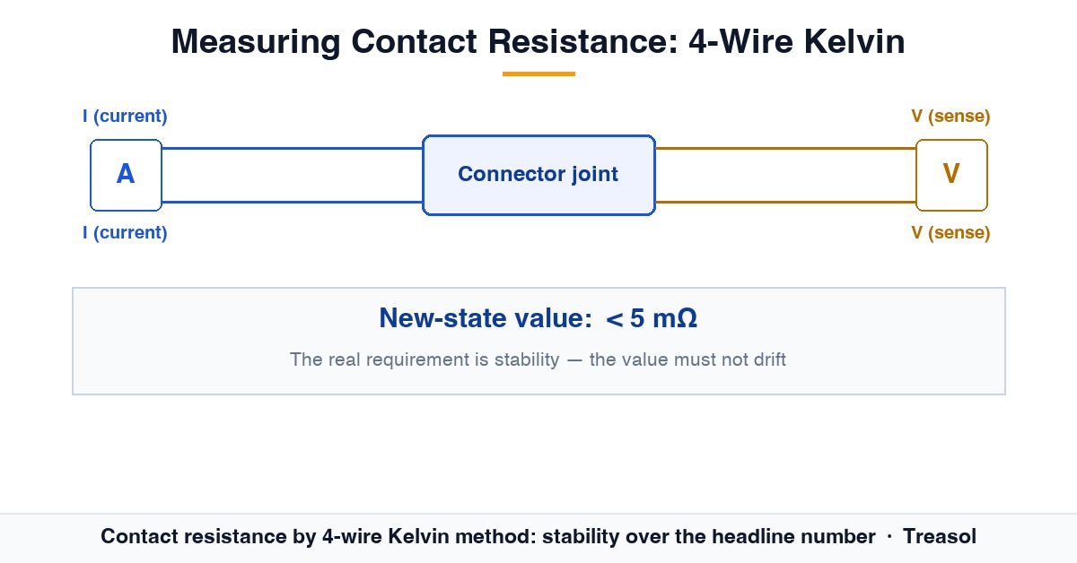
A connector that reads 0.35 mΩ fresh but climbs past 5 mΩ after 1000 hours of damp heat is worse than one that reads a shade higher new and holds. Ask suppliers for the post-test value, not the catalogue headline.
4. What type tests cannot catch: field reliability
This is the gap that burns arrays. Type tests run on laboratory samples under controlled schedules. They say nothing about what happens once a crew terminates the part on a roof.
4.1 Crimp quality is the dominant failure mode
A poor crimp raises the contact resistance at the metal interface. Under load, that joint dissipates heat as P = I²R. A 50 mΩ joint carrying 8 A sheds about 3.2 W into a few square millimetres; the contact surface can exceed 150 °C, the housing softens, the seal fails, moisture gets in, resistance climbs further — a self-feeding loop. Unlike AC, a DC arc does not cross zero and will not self-extinguish; it can hold for hours behind a panel.
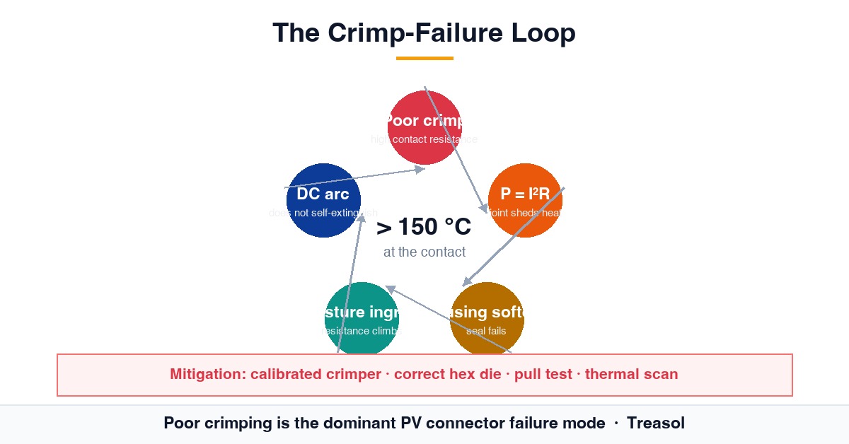
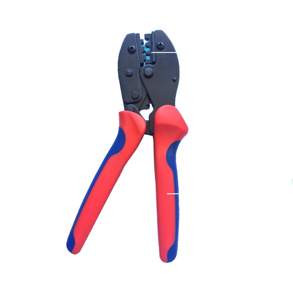
IEA PVPS failure analyses identify incorrectly crimped or fitted connectors as the root cause of connector-initiated power loss, arcing and fire. Field-installed connectors are consistently more vulnerable than factory-leaded module connectors. The mitigation is procedural and cheap: a calibrated ratcheting crimper with the correct hex die, a 6.0–7.5 mm strip length, a sample pull test (commonly ≥ 310 N at the cable-to-contact interface), and a thermal scan of the array under load before handover.
4.2 Cross-mating different brands (NEC 690.33)
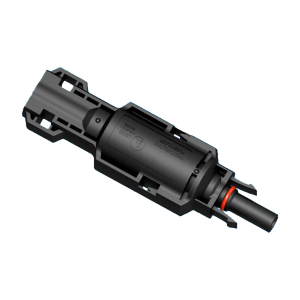
"MC4-compatible" does not mean "intermateable". The original MC4 geometry is widely cloned, but microscopic differences in contact shape, plating and seal dimensions produce high-resistance joints and broken seals. NEC 690.33(C) requires mated PV connectors to be the same type from the same manufacturer, or specifically listed and identified as intermateable. Field studies repeatedly trace rooftop arc faults to cross-mated connectors. The compliance evidence is the manufacturer's UL listing or intermateability certificate — not "they clicked together".
The procurement fix is simple: specify one connector family per project, ship housings, contacts, glands and tools together per crew, and keep communal bins out of the yard.
4.3 Long-term drift
Recent 2024–2025 research shows contact resistance in field-aged connectors rises under fretting, corrosion and dust, with measurable annual energy loss per string and a sharp failure transition once a critical amplitude is crossed. This is why EU bankability reports attribute 12%–29% of PV fires to connectors, why German data (1995–2012) put connectors behind 24% of 180 PV fires, and why a 2024 NREL study of 50,000+ O&M tickets across 837 U.S. sites found each connector failure takes a full string offline, with a median downtime of 191 hours.
The industry response is a universal connector standard, IEC 63678 (Standardised Plug and Socket Design for DC PV Systems), in development since 2023 — intended to remove the tolerance lottery that makes mixed brands dangerous.
5. How to qualify a PV connector supplier
A working checklist for EPCs and procurement:
- Request the IEC 62852 + UL 6703 test report from an accredited lab, not just a mark.
- Confirm the voltage and current rating clears your string (1000 V or 1500 V DC; from ~20 A up to 70 A depending on contact and wire gauge).
- Verify IP68 to IEC 60529 and glow-wire 850 °C for the housing.
- For agrivoltaics / floating PV, ask for IEC 62716 (ammonia) and salt-mist evidence.
- Demand the intermateability certificate if more than one brand will ever meet.
- Require batch traceability and a documented crimp + pull-test + thermal-scan QA protocol at commissioning.
6. Treasol PV connectors
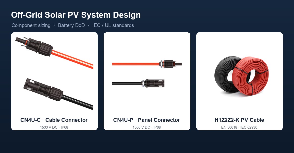
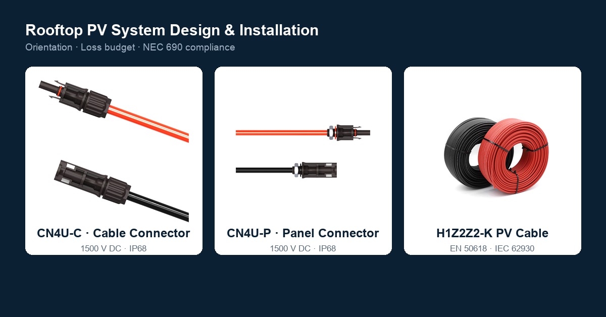
Treasol's MC4-compatible PV connectors — the CN4U-C cable connector and CN4U-P panel connector — are built for 1500 V DC systems with IP68 sealing and TÜV / UL / CE / RoHS compliance, and are qualified against IEC 62852 / UL 6703. Pair them with H1Z2Z2-K solar PV cable from the PV cable category, and review the MC4-compatible connector guide and the PV connector manufacturing process for crimping and QA detail. Standardizing on a single Treasol family per project satisfies NEC 690.33(C) and removes the cross-mating risk entirely.
7. Frequently Asked Questions
What standard governs PV connector testing?
IEC 62852 is the global reference; UL 6703 is the North American equivalent. Both define the electrical, mechanical, environmental and flammability tests a qualified PV connector must pass.
What is an acceptable contact resistance for a PV connector?
Measured by the 4-wire Kelvin method, a typical new-state value is below 0.5 mΩ — well into sub-milliohm territory. The real requirement is stability — the value must not drift out of tolerance through mating cycles, thermal cycling and corrosion.
What does IP68 mean for a solar connector?
Per IEC 60529, IP68 means dust-tight and protected against continuous immersion beyond 1 m. IP67 covers only temporary immersion and is the lower bar.
Can I mix MC4 connectors from different brands?
Not safely or code-compliantly. NEC 690.33(C) requires mated connectors to be the same type from the same manufacturer, or listed as intermateable. Look-alike clones can click together yet form high-resistance, leaky joints — a leading cause of rooftop arc faults.
Why do PV connectors fail in the field even after passing type tests?
Type tests qualify the product in a lab; they do not govern field workmanship. The dominant field causes are poor crimping (rising contact resistance leading to heat and DC arc) and cross-mating different brands. Proper tools, torque, pull tests and thermal commissioning scans close the gap.
How should I qualify a PV connector supplier?
Request the IEC 62852 / UL 6703 accredited test report, confirm the 1000/1500 V and current ratings, verify IP68 and glow-wire, ask for ammonia/salt-mist evidence where relevant, and require an intermateability certificate plus batch traceability and a commissioning QA protocol.
8. Conclusion
A PV connector is qualified by IEC 62852 and UL 6703 through electrical, mechanical, environmental and flammability tests — but those tests end at the laboratory door. Real-world reliability is won or lost at the crimp and at the mating decision. Specifying a single, fully certified connector family, demanding the accredited test report, and enforcing crimp + pull-test + thermal-scan QA is what keeps a 25-year array off the fire-investigation list.
Published by Dongguan Treasun New Energy Technology Co., Ltd, manufacturer of MC4-compatible solar PV connectors, junction boxes and photovoltaic DC cables certified to TÜV, UL, CE and RoHS.
References
- IEC 62852:2019 — Connectors for DC-application in photovoltaic systems — Safety requirements and tests.
- UL 6703 — Standard for Connectors for Use in Photovoltaic Systems.
- IEC 60529 — Degrees of protection provided by enclosures (IP Code).
- IEC 62930 / EN 50618 — H1Z2Z2-K photovoltaic cable; IEC 60228 — Conductors of insulated cables.
- IEC 62716 — Ammonia environment testing (agrivoltaics / fishery-PV).
- ISO 9227 — Salt spray corrosion tests; IEC 60068-2-52 — Salt mist; IEC 60068-2-43 / -60 — Gaseous corrosion.
- IEC 60695-2-11 — Glow-wire flammability; UL 94 — Flammability of plastic materials.
- NFPA 70 — National Electrical Code, Article 690.33 (PV connector interconnection).
- TÜV 2 PfG 2740 / 2 PfG 1169 — PV connector component specifications.
- Kapoor, K. et al. (2024/2025), "Study on Reliability of Field-Aged Photovoltaic Connectors," Eksploatacja i Niezawodność – Maintenance and Reliability, vol. 27(3).
- PV-Tech (2025), "The illusion of simplicity: Why PV DC connector failures remain a persistent challenge."
- NREL (2024), O&M ticket analysis across 837 U.S. sites (connector failure downtime and capacity loss).
- IEC 63678 (in development, since 2023) — Standardised Plug and Socket Design for DC PV Systems (NREL-led drafts).