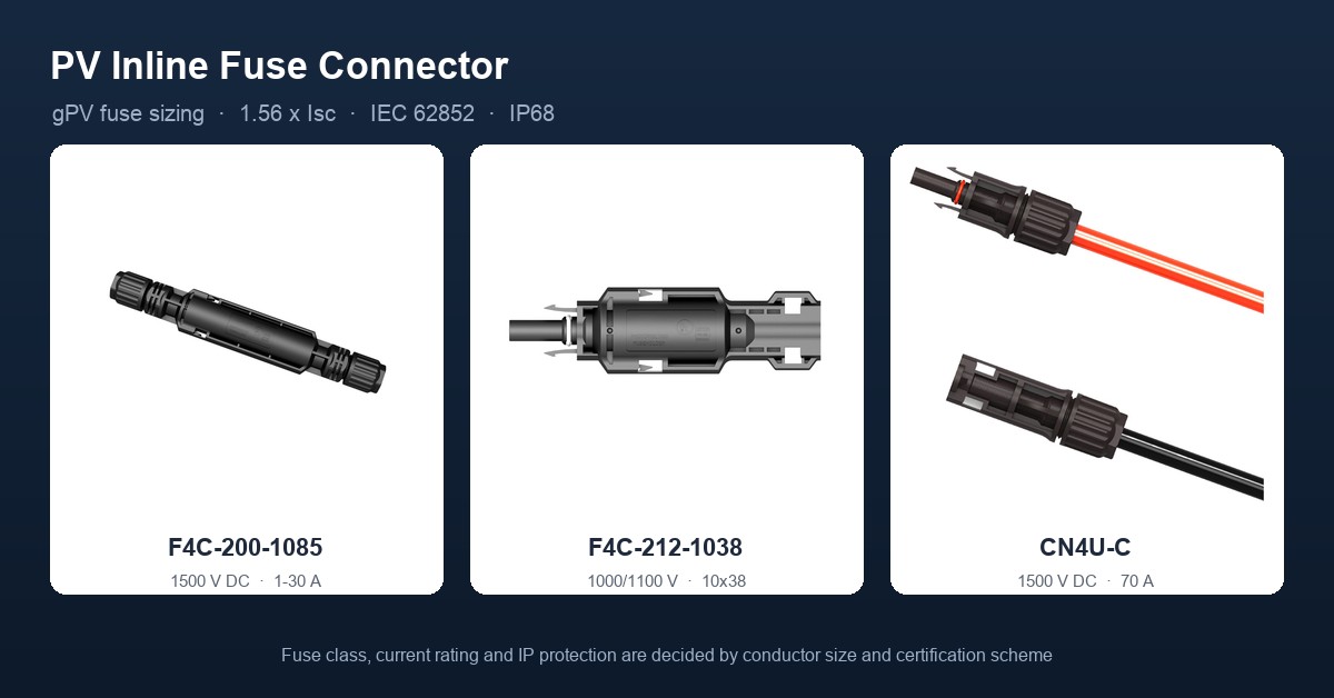
A PV inline fuse connector is a connector body with a gPV fuse-link built into it, installed in series with a module string on the DC side of an array. It opens the circuit when reverse current from parallel strings, an internal short or a ground fault would otherwise drive current through conductors that were never sized for it. Four parameters define the part: rated voltage (1000 V or 1500 V DC), rated current (set by conductor cross-section and certification scheme), degree of protection (IP67 or IP68), and contact resistance (0.5 mΩ or less when new).
1. What the fuse actually protects
A PV module is a current source, not a voltage source. Its output does not collapse when a fault appears; it keeps pushing whatever current the irradiance allows. That behaviour is why a faulted string is dangerous in a way a faulted AC circuit is not.
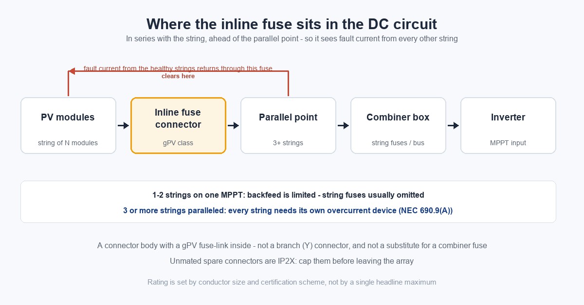
Take ten strings of 12 A Isc paralleled on a combiner bus, with one string shorted inside a module. The other nine strings do not know about the fault. They feed roughly 108 A into the fault path, and that current passes through cable and connectors selected for about 19 A. Nothing in the string itself limits it. The inline fuse is the only device in that path whose job is to open before the insulation fails.
Where only one or two strings land on the same MPPT, the available backfeed is bounded by the healthy string's own short-circuit current, and string-level fusing is normally omitted. From three parallel strings upward, every string needs its own overcurrent device (NEC 690.9(A)).
The decision table for that threshold, and how the three F4C body sizes and voltage classes compare, sits in a separate article on solar fuse connector selection. This page stays on the electrical and mechanical side: how to size the fuse, how to terminate the connector, and what makes one fail in service.
2. Voltage and current ratings: tied to conductor size
A connector's ampacity is not a standalone number. It is fixed by the cross-section it terminates and by the certification scheme the part is listed under, because the IEC and UL test regimes use different conductor tables and different temperature-rise limits. Published data for the Stäubli MC4-Evo 2, the reference product in this class:
| Scheme | Conductor | Rated current | Rated voltage |
|---|---|---|---|
| IEC 62852 | 4 mm² | 45 A | DC 1500 V |
| IEC 62852 | 6 mm² | 53 A | DC 1500 V |
| UL 6703 | 12 AWG | 35 A | DC 1500 V |
| UL 6703 | 10 AWG | 50 A | DC 1500 V |
Two readings follow from that table. First, a headline figure such as "1500 V / 65 A" for a generic inline fuse connector sits above what this class of product is tested to, and usually traces back to a marketing sheet rather than a test report. Second, the same connector carries 45 A or 35 A depending on which scheme the project is inspected against — so the rating has to be quoted together with the conductor and the market.
Fuse-connector assemblies follow the same logic. The solar fuse connector range splits 1500 V DC bodies for 10.3×85 mm links from 1000/1100 V bodies for 10.3×38 mm links, and the voltage class is a property of the assembly, not something the installer selects at the bench.
3. Fuse sizing: 1.56 × Isc, not 1.25 × Isc
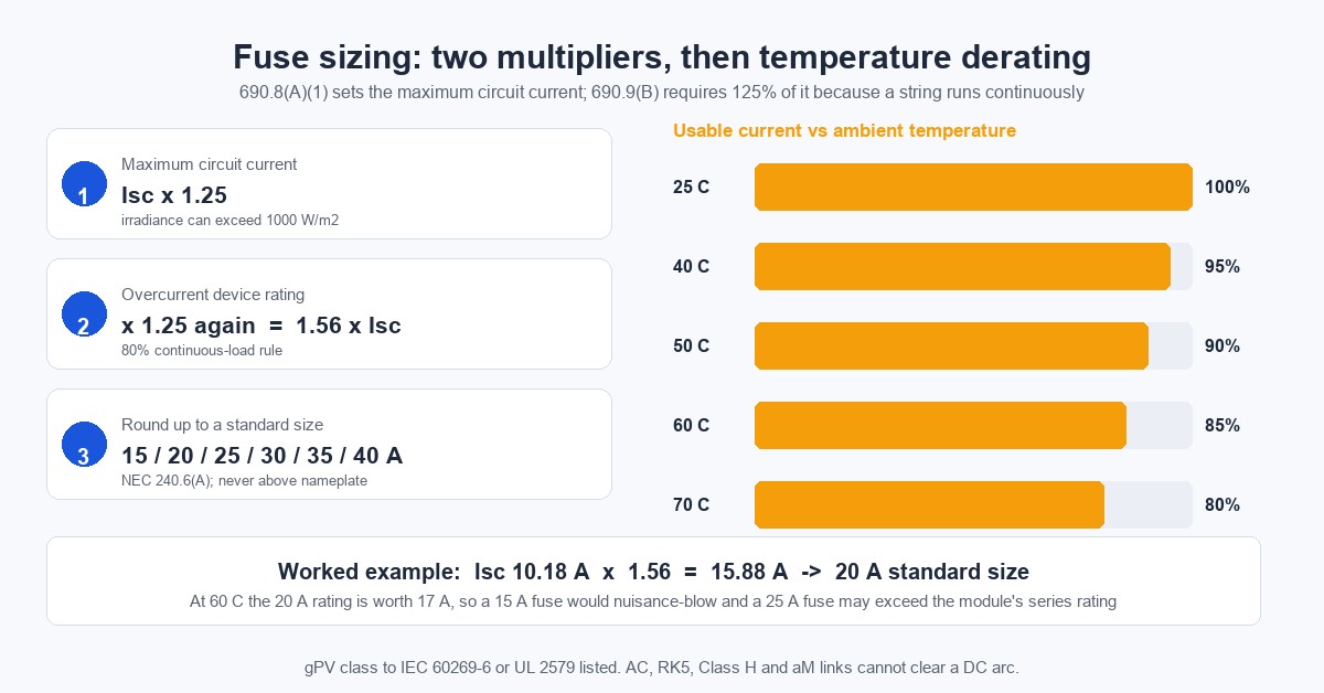
This is where sizing most often goes wrong. The two multipliers are sequential, not alternatives: applying only the first one leaves the fuse below the code minimum.
- NEC 690.8(A)(1) sets the maximum circuit current at Isc × 1.25, because irradiance above the 1000 W/m² standard test condition can push string current higher than the nameplate value.
- NEC 690.9(B) requires the overcurrent device to be rated at not less than 125% of that current, because a PV string carries current for more than three hours at a stretch and standard devices are rated for 80% continuous loading.
Combined: I_fuse ≥ Isc × 1.56, then rounded up to the next standard rating in NEC 240.6(A) — 15, 20, 25, 30, 35, 40 A and upward.
Worked example. A module with Isc = 10.18 A and a nameplate maximum series fuse rating of 20 A. 10.18 × 1.56 = 15.88 A, which rounds to 20 A. That value also sits exactly at the nameplate ceiling, so the string is compliant. Had the calculation landed on 25 A, the module would have been the binding constraint and the array would need a different string length or a module with a higher series rating.
Three constraints govern the result:
- The nameplate maximum series fuse rating is a ceiling, not a target. Exceeding it voids the module warranty and, more importantly, means the fuse no longer protects the module's internal wiring.
- Temperature derating applies. Fuse ratings are referenced to 25 °C. A combiner box in summer runs at 50–70 °C, so the usable current at 60 °C is 85% of the nameplate figure — a 20 A fuse behaves like a 17 A fuse. A string that was marginal at 25 °C will nuisance-blow in July.
- The link must be gPV class to IEC 60269-6, or listed to UL 2579. AC fuses, Class RK5, Class H and aM links are not acceptable, because a DC arc has no zero crossing and a device that relies on current reversal to extinguish the arc will keep conducting inside its holder.
4. IP68 applies only when mated
| Condition | Rating | Note |
|---|---|---|
| Mated, same brand, correctly crimped | IP68 (1 m, 168 h); some types also list IP65 | IEC 60529 |
| Unmated | IP2X | Fit sealing caps on any connector left open outdoors |
The waterproofing comes from the connector's integrated O-rings and silicone seals, plus a cable gland tightened to the specified torque. It does not come from heat shrink tubing. Heat shrink is not rated for 25 years of outdoor UV exposure, it cannot be inspected once fitted, and applied over a gland it can trap a water pocket against the joint instead of sealing it.
The distinction matters at handover. A spare string left unterminated on a roof, with the connector body open, is at IP2X. Water enters, the tin-plated contact oxidises over a season, and the resistance goes up before the array is even commissioned. Sealing caps cost almost nothing and are the cheapest reliability measure on the site. For the interface itself, see the MC4-compatible connector page.
5. Current-carrying capacity and derating
Rated current is defined for stated ambient and installation conditions. Derate when any of the following applies:
- ambient temperature exceeds the reference band — typically −40 to +85 °C, with an upper limiting temperature around 115 °C at the contact;
- cables are bundled, pulled through conduit, or laid in tray with restricted airflow;
- the run passes through rooftop metal conduit, where internal temperatures exceed 70 °C in summer;
- the site is at altitude, where thinner air reduces convective cooling.
The common failure here is not a wrong calculation but a missing one. A 6 mm² string selected at 53 A on the bench, run in a bundled conduit on a dark roof, is no longer a 53 A connection. Where the installation cannot be changed, the conductor goes up a size.
6. Contact resistance and temperature rise
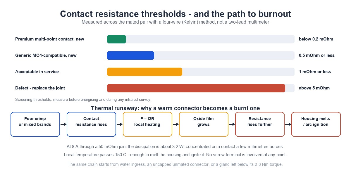
| Condition | Contact resistance |
|---|---|
| Premium multi-point contact, new | below 0.2 mΩ |
| Generic MC4-compatible, new | 0.5 mΩ or less |
| Acceptable in service | 1 mΩ or less |
| Defect — replace the joint | above 5 mΩ |
Heating follows P = I²R. An 8 A string current through a 50 mΩ defective joint dissipates about 3.2 W on a contact area a few millimetres across — enough to push local temperature past 150 °C and melt the housing.
Heat accelerates oxidation, oxidation raises resistance, and the loop reinforces itself. That is the physical path from a connector that reads slightly warm in an infrared survey to one that burns through a year later. It also explains why the first inspection matters more than the tenth: the defect is cheap to find at 1 mΩ and impossible to repair at 50 mΩ.
Measurement discipline is part of the specification. A two-lead multimeter includes the resistance of its own leads and probes, which is the same order of magnitude as the value being measured, so it cannot validate a milliohm joint. Use a four-wire (Kelvin) method, and record the reading against the string and the ambient temperature.
7. Crimping: the step that decides service life
MC4-family connectors do not use screw terminals. There is no terminal block, no set screw, and no screwdriver step anywhere in the assembly. The sequence is:
- Strip to the manufacturer's length — typically 13–15 mm of conductor and 50–60 mm of outer jacket. Both over-stripping and under-stripping cause failures: too much bare conductor and the strands spread inside the contact; too little and the contact crimps onto insulation.
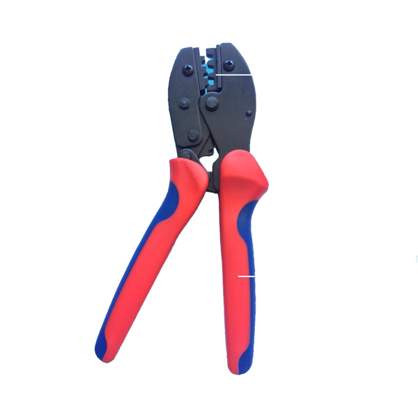
- Crimp with a ratchet crimper and a die matched to both the contact and the conductor size (IEC 60352-2). A ratchet will not release until the full crimp cycle completes, which is the point of using one. Pliers, vice grips and mismatched dies produce a joint that is mechanically tight and electrically poor.
- Insert and lock the contact until it seats with an audible click, then verify retention by pulling. IEC 62852 type testing requires 50 N cable retention; field sampling commonly applies 310 N.
- Tighten the cable gland to 2–3 N·m with a torque wrench. Hand-tight is not a specification, and over-torque damages the seal it is meant to protect.
- Never connect or disconnect under load. A DC arc does not self-extinguish at a current zero, because there is no current zero.
Brand consistency belongs in the same list. Connectors are certified as a mated system, and mixing brands is prohibited under NEC 690.33 and UL 6703; Stäubli states plainly that its certification does not cover intermating with other makes. The mechanical interface may look identical, but contact geometry, tolerance and spring force differ by fractions of a millimetre — which is exactly the scale at which contact resistance is decided.
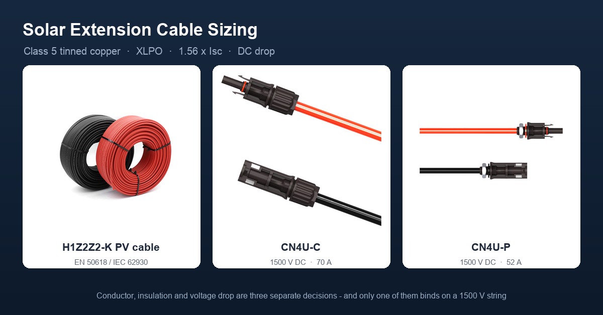
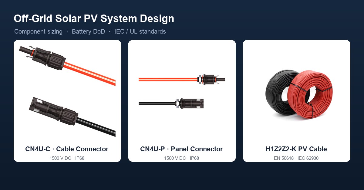
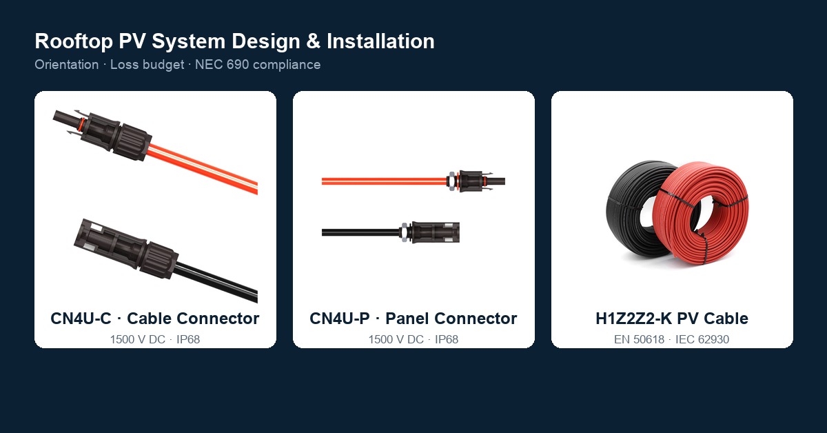
Treasol builds its DC connection range to these requirements. The CN4U-C cable connector and CN4U-P panel connector are MC4-compatible and rated for 1500 V systems, and pair with H1Z2Z2-K PV cable built to EN 50618 / IEC 62930. Terminate them with a matched die and a ratchet tool; an unmatched die will not produce a gas-tight crimp.
8. Failure modes and what causes burnout
| Failure mode | Direct cause | Consequence |
|---|---|---|
| Poor crimp | Non-ratchet tool, mismatched die, wrong strip length | Rising contact resistance, local overheating, melted housing |
| Cross-brand intermating | Contact geometry, tolerance and spring force do not match | Reduced contact area, overheating, water ingress |
| DC arc | Disconnecting under load, loose joint, damaged insulation | Arc does not self-extinguish; fire |
| Water ingress | Gland below torque, aged seal, uncapped unmated connector | Electrochemical corrosion, rising resistance |
| Wrong fuse | AC or aM link, undersized rating, no temperature derating | Fails to clear, or nuisance blowing |
| Material ageing | Non-UV-stabilised housing, sustained high temperature | Cracking, discolouration, loss of insulation |
Published field data supports the ranking. Connector-related failures account for 12%–29% of PV fires in European bankability reporting; 24% of the 180 PV fires recorded in Germany between 1995 and 2012 originated in connectors; and an NREL analysis published in 2024, covering 837 sites and more than 50,000 maintenance tickets, found that a single connector failure can take an entire string offline, with a median outage of 191 hours.
Those figures are worth quoting with their caveats. They come from different populations, use different denominators, and none of them isolates inline fuse connectors from the wider connector population. What they do establish is the order of magnitude: connector failures are not a cosmetic issue, and the downtime they cause is measured in days.
9. Installation and maintenance checks
| Stage | Action | Acceptance |
|---|---|---|
| Design | Size the gPV fuse at 1.56 × Isc and apply temperature derating | Within the module nameplate maximum |
| Assembly | Ratchet crimp with matched die; sample retention pulls | 50 N type test / 310 N field |
| Assembly | Cable gland torque | 2–3 N·m |
| Before energising | Four-wire contact resistance, insulation resistance, polarity | 1 mΩ or less |
| Routine | Annual visual inspection plus infrared survey | Any string temperature anomaly investigated |
| Harsh sites | Semi-annual inspection | Coastal, desert, high-pollution |
Clean contacts and housings with isopropyl alcohol and a soft brush, and let the joint dry completely before reassembly. A housing showing cracking, discolouration or a melt mark is replaced, not repaired. There is no field repair for a connector that has already arced — the damage is inside the contact, where it cannot be seen.
10. Selection quick reference
| Application | Specification |
|---|---|
| Residential, up to 2 strings per MPPT | 1000 V, 4 mm²; string fuses usually not required |
| Residential and C&I, 3+ strings | 1500 V, 4–6 mm²; 15–30 A gPV fuse per string |
| Ground-mount, long homeruns | 1500 V, 6–10 mm²; fuse at 1.56 × Isc |
| Coastal, salt mist | Tinned copper contacts, IP68, ammonia resistance (e.g. TÜV 2 PfG 1911) |
| Desert, high temperature | Larger conductor or derated current; UL94 V-0 housing |
Body size follows the link, not the roof. The F4C-200-1085 and F4C-201-1085 take 10.3×85 mm links and are rated 1500 V DC / 1–30 A; the F4C-212-1038 takes a 10.3×38 mm link and is rated 1000/1100 V. Pair the body to the system voltage first, then select the link current from the calculation above. Where the array feeds several combiners across a large site, the connector manufacturing page covers the assembly and test side.
FAQ
How do I size the fuse in a PV inline fuse connector?
Under NEC 690.8(A)(1) and 690.9(B), I_fuse is at least Isc × 1.56, rounded up to the next NEC 240.6(A) standard size. It must not exceed the module's maximum series fuse rating, and it must be derated for the actual enclosure temperature.
Can I use a standard AC fuse in a PV string?
No. DC current has no zero crossing, so an AC-rated fuse cannot reliably extinguish the arc and may sustain it inside the holder. Use gPV fuse links to IEC 60269-6 or devices listed to UL 2579.
What contact resistance is acceptable for an MC4 connector?
New connectors are typically 0.5 mΩ or less, with premium multi-point designs below 0.2 mΩ. In service, 1 mΩ or less is acceptable; above 5 mΩ the joint is defective and should be replaced. Measure with a four-wire method.
Can MC4 connectors from different brands be mated?
No. NEC 690.33 and UL 6703 require connectors to be used within their certified mating combination, and Stäubli states its certification does not cover intermating with other makes. Intermating is a leading cause of field failures.
Does IP68 mean the connector can sit in water permanently?
No. IP68, for example 1 m for 168 h, applies only in the mated condition with a matching brand and a correctly crimped, correctly torqued gland. Unmated connectors are IP2X and need sealing caps outdoors.
How often should PV connectors be inspected?
The common practice is an annual visual inspection combined with an infrared survey. Coastal, desert and high-pollution sites justify semi-annual or quarterly checks. Any temperature anomaly within a string warrants immediate investigation.
Why do PV connectors burn out?
The mechanism is P = I²R heating followed by thermal runaway. A poor crimp, cross-brand intermating, corrosion from water ingress, or an arc drawn by disconnecting under load raises a milliohm-level resistance into a hot spot well above 150 °C, which melts the housing and can ignite it.
References
- IEC 62852:2014+Amd.1:2020 — Connectors for DC application in photovoltaic systems: safety requirements and tests
- UL 6703 — Connectors for use in photovoltaic systems
- IEC 60269-6 — Low-voltage fuses: supplementary requirements for fuse-links for the protection of solar photovoltaic energy systems (gPV)
- UL 2579 — Low-voltage fuses for photovoltaic systems
- IEC 60529 — Degrees of protection provided by enclosures (IP code)
- IEC 60352-2 — Solderless connections: crimped connections
- IEC 62446-1 — PV systems: requirements for testing, documentation and maintenance
- IEC 60364-7-712 — Low-voltage electrical installations: PV power supply systems
- IEC 62548 — Photovoltaic arrays: design requirements
- IEC TS 63126 — Temperature testing and classification
- NEC Articles 690.8, 690.9, 690.33 and 240.6(A) — NFPA 70
- TÜV Rheinland 2 PfG 1911/03.2011 — ammonia resistance for PV connectors
- UL 94 — flammability classification of plastic materials
- Stäubli MC4-Evo 2 datasheets (PV-KST4/6I-UR): IEC 62852 DC 1500 V / 45 A (4 mm²), 53 A (6 mm²); UL 6703 35 A (12 AWG), 50 A (10 AWG); contact resistance below 0.2 mΩ; IP65/IP68 (1 m, 168 h) mated, IP2X unmated; −40 to +85 °C
- NREL (2024) — operations and maintenance analysis across 837 sites and 50,000+ tickets; median outage 191 hours per connector failure
- IEA PVPS Task 13 — PV module and system reliability, connector field failures
Prepared by Treasun New Energy Technology Co., Ltd — manufacturer of MC4-compatible PV connectors, fuse connectors, junction boxes and H1Z2Z2-K photovoltaic cable.