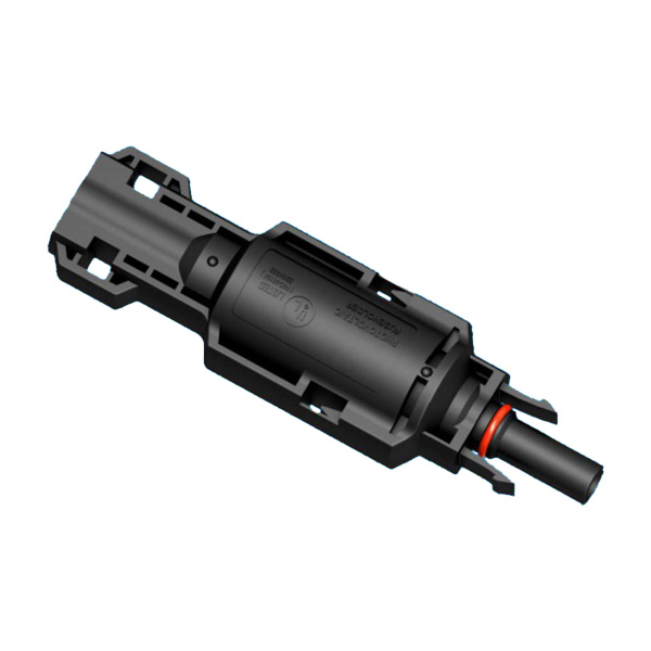
Ask an operations and maintenance technician which component fails most often in a rooftop array and the answer is rarely the module. It is the small inline part in the DC harness that nobody thinks about until it opens — the fuse connector. When it is sized correctly, it is invisible. When it is the wrong size, it either nuisance-trips on a clear day or sits there letting a fault current run straight past its rating.
This guide walks through the four decisions that actually determine which solar fuse connector you should specify: whether you need one at all, the fuse body size, the voltage class, and the fuse current. Every number below is taken from the Treasol F4C series datasheet, so the values you read here are the same values printed on the product pages.

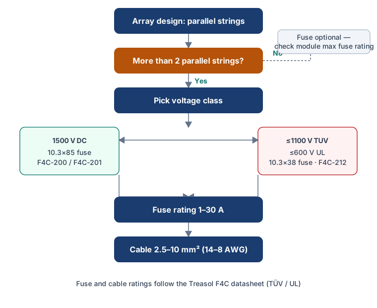
When does a string actually need a fuse?
A fuse connector is not a universal requirement. A single string, or two strings in parallel, generally does not need one. The moment you parallel three or more strings into a common DC bus, the failure arithmetic changes. If one string develops a short circuit, every other healthy string feeds current backward into the faulted circuit. That reverse current can exceed the maximum series fuse rating printed on the module label, and then the module's own conductors and junction box become the weak point.
This is why the relevant codes require overcurrent protection on parallel source circuits: NEC 690.9 in North America and IEC 62548 elsewhere both call for protection where the available fault current from parallel strings can exceed the rating of the conductors or equipment downstream. A fuse connector places that protection exactly where it belongs — inline, in the string, before the fault current ever reaches the combiner.
If you are not sure, the simple test is this: count the parallel strings. Two or fewer, and a fuse is usually optional (still check the module's maximum series fuse rating). Three or more, and each string should carry its own fuse.
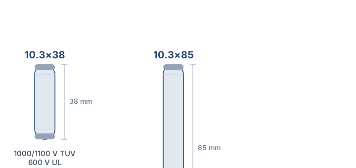
Fuse body size: 10.3×85 vs 10.3×38
The first number that separates the F4C range is the physical fuse body. Treasol builds the F4C around two standard PV fuse sizes: 10.3×85 and 10.3×38. The first figure is the body diameter in millimetres, the second is the length. The two bodies are not interchangeable — a 38 mm fuse will not seat in an 85 mm holder, and the larger body is not simply a longer version of the small one. They are built for different voltage classes, which is the next decision.
| Specification | 10.3×85 — F4C-200 / F4C-201 | 10.3×38 — F4C-212 |
|---|---|---|
| Fuse body | 10.3×85 mm | 10.3×38 mm |
| Fuse current range | 1–30 A | 1–30 A |
| Rated voltage (TUV) | 1500 V | 1000/1100 V |
| Rated voltage (UL) | 1500 V | 600 V |
| Ingress protection | IP68 | IP68 |
| Contact resistance | <0.5 mΩ | <0.5 mΩ |
| Cable cross-section | 2.5/4.0/6.0/10.0 mm² (14/12/10/8 AWG) | 2.5/4.0/6.0/10.0 mm² (14/12/10/8 AWG) |
| Insulation material | PPE | PPE |
| Contact material | C3602, tin plated | C3602, tin plated |
| Flame class | UL 94-V0 | UL 94-V0 |
The two 85 mm models are electrical twins — F4C-200-1085 and F4C-201-1085 carry the same ratings and differ in housing detail, so the choice between them is a mechanical one. The 38 mm model is a different product: F4C-212-1038, rated for the lower voltage class described below.
Voltage class: 1500 V vs 1000/600 V
This is where most specification mistakes happen, because a fuse connector carries two voltage ratings and the two are not the same number.
The TUV rating follows the IEC 62852 / IEC 60269-6 world. The 85 mm F4C models are rated 1500 V under TUV and 1500 V under UL, which makes them the correct choice for 1500 V DC utility and large commercial systems. The 38 mm F4C-212 is rated 1000/1100 V under TUV but only 600 V under UL. If you are wiring a North American project, the UL number is the one that matters, and for the 38 mm body that number is 600 V — not 1000 V.
Read the two figures together. A part that is sold as a 1000 V connector on the datasheet front page may be a 600 V connector in front of a North American inspector. When in doubt, match the fuse body to the voltage class first, and only then look at current.
Fuse current: 1–30 A
Both F4C bodies accept fuse elements rated from 1 A to 30 A. Choosing the right element is a short calculation with two well-known factors from the code.
Start with the string's short-circuit current under the worst-case conditions the site will actually see — high irradiance and low temperature, not nameplate. Where the governing code requires it, apply the NEC 690.9 factors: multiply by 1.25 for continuous duty and, where the applicable code edition and equipment marking specify it, by a second 1.25 for irradiance above the reference condition — a combined 1.56 factor. The fuse you select must carry that adjusted current continuously and still open fast enough on a real fault.
The practical result is that the fuse rating sits above the operating current and below the module's maximum series fuse rating. If the two leave you no room, the array configuration — not the fuse — is what needs to change.
Cable cross-section: 2.5–10 mm²
The F4C series accepts conductor cross-sections of 2.5, 4.0, 6.0 and 10.0 mm², which map to 14, 12, 10 and 8 AWG. The connector does not decide the cable for you — the cable size comes from the current and the voltage-drop budget of the run, and the connector simply has to accept that conductor and terminate it cleanly.
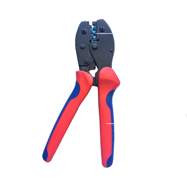
A mismatch here is a common field failure. If you force a 10 mm² conductor into a terminal rated for a smaller cross-section, or crimp an oversized terminal onto an undersized conductor, the contact is poor and the joint runs hot. Choose the cable first with a sizing guide, then confirm the connector accepts it. For the full sizing logic see our PV DC cable sizing guide, and for the crimp itself see PV cable installation.

Frequently asked questions
When is a fuse connector required in a solar array?
Do not decide string overcurrent protection from string count alone. Determine the maximum available reverse current into a faulted string, apply the governing code and design factors, and compare the result with the module maximum series fuse rating and the ratings of the conductors and downstream equipment. In many designs, three or more strings paralleled into a common DC bus warrant string-level fusing, while two strings or fewer generally do not — but the module label and the applicable code remain the authority.
What is the difference between a 10.3×85 and a 10.3×38 fuse connector?
The two bodies differ in length — 85 mm versus 38 mm — and in voltage class. The 10.3×85 F4C models are rated 1500 V under both TUV and UL, while the 10.3×38 F4C-212 is rated 1000/1100 V under TUV and 600 V under UL. Both accept 1–30 A fuse elements and the same 2.5–10 mm² cable range.
Can a 1500 V fuse connector be used on a 600 V system?
Yes. A connector rated for a higher voltage may be usable at a lower voltage, but only within its certification scope, cable compatibility, and the applicable design and installation conditions. The reverse is not true — a 600 V UL rated connector must not be used on a higher-voltage circuit. Using the higher-rated part on a lower-voltage system costs a little more but is electrically safe.
What fuse current should I choose for my strings?
Where the governing code requires it, apply the NEC 690.9 factors to the string's short-circuit current at worst-case irradiance and temperature: multiply by 1.25 for continuous duty and, where the applicable code edition and equipment marking specify it, by a second 1.25 for irradiance above the reference condition, a combined 1.56 factor. The selected fuse must carry that current continuously while staying below the module's maximum series fuse rating.
Still not sure which model fits your array? The full solar fuse connector range lists the three F4C variants side by side, or reach out through the contact page with your string voltage and parallel count and we will match the right body and fuse rating.