Fire statistics for photovoltaic systems are published irregularly, come from different sources, and are almost always reported without the number that makes them readable: how many systems are actually operating. This article puts one recent dataset on the table, writes the denominator next to it, and then looks at what the distribution of causes means for the part of the DC chain that procurement can still influence.
The dataset is QBE's analysis of UK solar PV fires, reported by pv magazine and the UK Fire Protection Association in 2026. It is the most detailed breakdown of PV fire causation available publicly, and it separates incidents by component rather than lumping them into "electrical."
1. How to read any PV fire statistic
Three questions have to be answered before a fire count means anything:
- Over what period, and in what population? A count of fires is meaningless without the number of systems in service during the same period.
- Is the cause attributed or unknown? Most datasets have a large "undetermined" bucket. The percentages that matter are the ones calculated over attributed causes only.
- Does "PV fire" mean the PV system caught fire, or that a fire started elsewhere and involved it? Those are different failure populations.
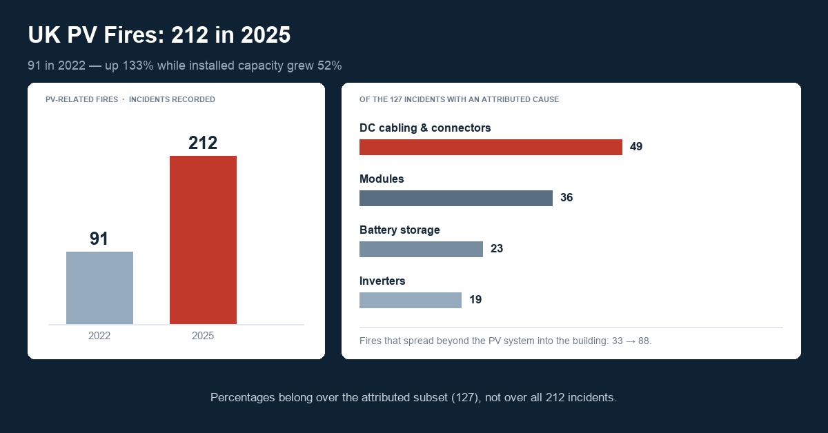
In the QBE dataset, 212 incidents were recorded in 2025 and causes were attributed in 127 of them. Every percentage below is calculated over the 127, not the 212, and this article follows that convention.
2. The numbers, with the denominator
- 212 PV-related fires in the UK in 2025, against 91 in 2022 — an increase of about 133%.
- Installed capacity grew 52% over the same period. The fire count is rising faster than the fleet.
- Of the 127 incidents with an attributed cause, 49 originated in DC cabling and connectors — the largest single category. The rest: 36 modules, 23 battery storage, 19 inverters.
- Fires that spread beyond the PV system into the building rose from 33 to 88.
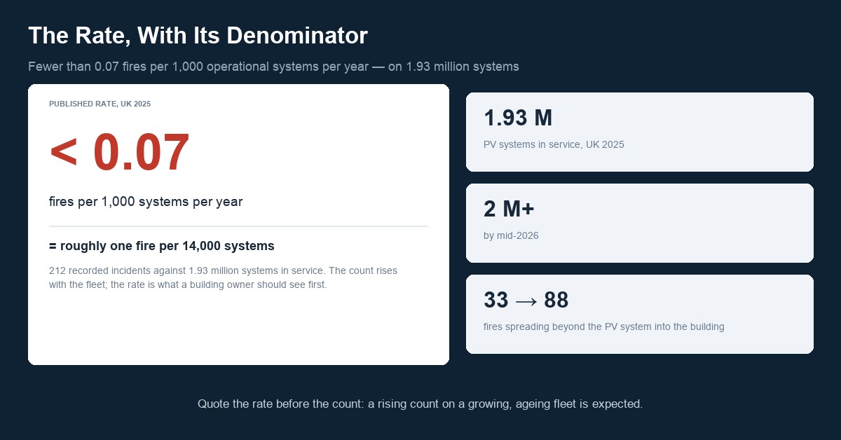
- The UK had roughly 1.93 million operational PV systems in 2025, passing 2 million by mid-2026.
- QBE puts the rate at fewer than 0.07 fires per 1,000 systems.
That last figure is the one to lead with in any conversation with a building owner. Fewer than seven fires per hundred thousand systems per year means PV remains, statistically, a low-frequency event. It is not a reason to discount the data — it is the reason the data can be discussed rationally instead of defensively.
3. Why the DC side leads the list
The ranking is not surprising once the physics is laid out. A DC arc behaves differently from an AC arc of the same voltage and current: there is no zero crossing, so once an arc establishes itself it does not self-extinguish every half cycle. A 1,000 V or 1,500 V string has more than enough open-circuit voltage to sustain an arc across a gap of a millimetre or two.
Connectors sit at precisely the point where that voltage meets a mechanical joint made by hand:
- They are the only current-carrying joints in the string that are not bolted or screwed. Contact force comes from a spring contact that has to survive thermal cycling, vibration and 25 years of UV.
- They are made on site. Crimp quality depends on the tool, the die, the operator and the cable batch. Tools drift out of calibration; dies wear.
- They are hidden. Most connectors sit behind the module, against the roof or under the array. A joint can run hot for months without anyone seeing it.
- They are the most likely place for two different manufacturers' parts to meet. Contact geometry, plating and seal compression are each controlled to one manufacturer's drawings; a mixed pair was tested by neither.
The failure progression is well documented and covered in more detail in Can Poor PV Connector Quality Cause Solar Fires?: elevated contact resistance produces local heating, heating accelerates oxidation of the contact surface, oxidation raises resistance further, and the housing softens and carbonises. Once the polymer carbonises it becomes conductive, tracking begins, and the joint becomes an ignition source rather than a hot spot.
4. From a hot joint to a fire
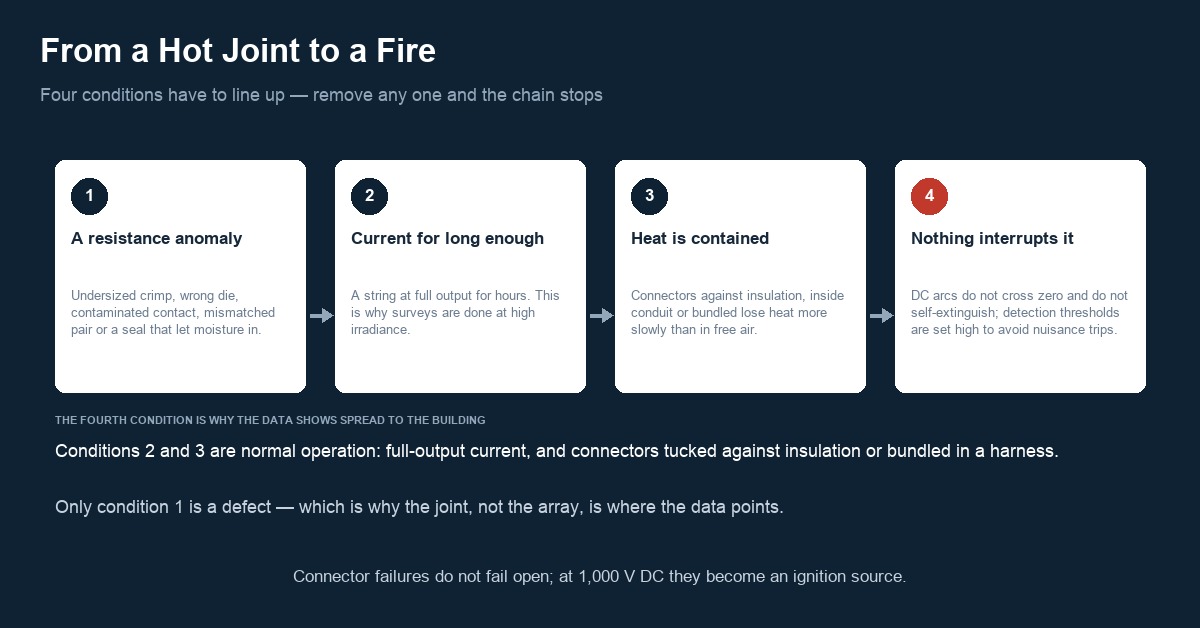
Four conditions have to line up. Remove any one and the chain stops.
- A resistance anomaly exists. Undersized crimp, wrong die, contaminated contact, mismatched pair, or a seal that let moisture in.
- Current flows for long enough to heat it. A string at full output for hours is the relevant condition, which is why thermographic surveys are done at high irradiance, not in the morning.
- The heat is contained. Connectors tucked against insulation, inside conduit or bundled in a harness lose heat more slowly than ones in free air.
- Nothing interrupts it. DC arcs do not self-extinguish. Ground-fault and arc-fault detection help, but detection thresholds are set to avoid nuisance tripping, and a series arc below the threshold will simply continue.
The rise in fires spreading to the building — 33 to 88 — is consistent with the fourth condition. Once ignition occurs in a roof-mounted system, the combustible path is the roof structure, not the array.
5. What insurers ask for
Insurance requirements vary by market and by underwriter, so the following is a pattern rather than a rulebook. What appears repeatedly in UK and European underwriting guidance:
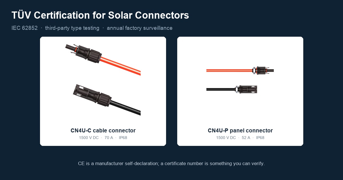
- Component certification against IEC 62852 or UL 6703, with a certificate that can be traced to the issuing body — see the certification overview.
- Installation to a recognised standard: MCS in the UK, the IET Code of Practice for grid-connected solar PV systems, and the RISCAuthority RC62 recommendations for fire safety in PV installations.
- Periodic thermographic inspection, typically annual for commercial arrays, with results retained. The method is set out in IEC TS 62446-3.
- Documented maintenance, including re-torque or re-termination where a survey finds elevated temperature.
- Correct DC cable specification: double-insulated, UV- and ozone-resistant cable rated for the system voltage, installed so it is not under mechanical tension at the connector.
What underwriters are not asking for is a particular connector brand. They are asking for evidence that the DC chain was built from certified parts, installed by people who were verified on the process, and inspected on a schedule. That is a documentation problem as much as an engineering one.
6. What procurement actually controls
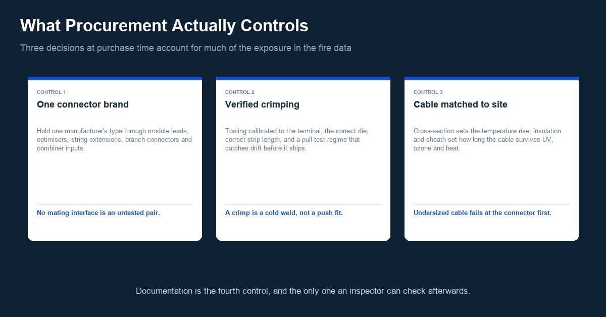
Three decisions at purchase time account for a large share of the exposure that shows up in the fire statistics.
One connector brand across the whole DC chain
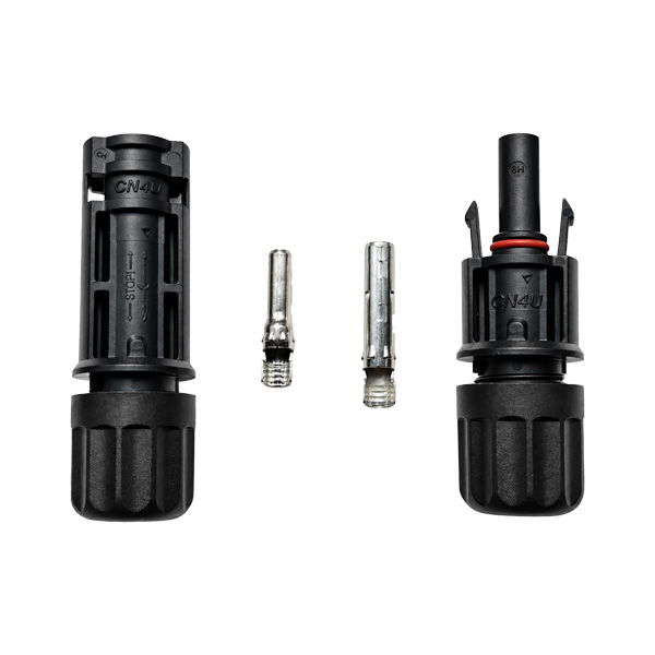
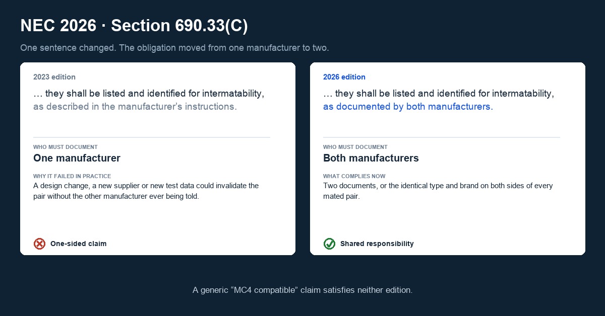
The largest attributable category in the dataset is DC cabling and connectors. The single cheapest control is to hold one manufacturer's connector type through module leads, optimisers, string extensions, branch connectors and combiner inputs, so that no mating interface is an untested pair. Our cross-mating analysis covers why a mixed pair is not covered by either manufacturer's certification.
Verified crimping, not assumed crimping
A crimp is a cold weld. Its quality depends on tooling calibrated to the terminal, the correct die, the correct strip length and a pull-test regime that catches drift before it ships. Factory-terminated harnesses can be sampled, sectioned and pull-tested on a statistical basis; field crimping is verified only if someone decided in advance to verify it. The tooling question is covered in the crimping tool guide.
Cable that matches the environment and the connector
Conductor cross-section sets the temperature rise at a given current; insulation and sheath set how long the cable survives UV, ozone and heat. A cable rated below the array's open-circuit voltage, or a sheath not rated for the site's UV load, fails at the connector first, because that is where the mechanical stress concentrates. Sizing and material selection are treated in PV DC Cable Sizing and Solar Panel Cable: Why H1Z2Z2-K Is the Standard.
7. What the data does not say
Two cautions keep this dataset useful rather than alarming:
The absolute rate is low. Fewer than 0.07 fires per 1,000 systems per year, on a fleet of nearly two million systems. PV is not a high-frequency fire source, and saying otherwise would misrepresent the numbers.
Correlation with fleet growth is not proof of declining quality. The fleet also got older. Systems installed in the 2010–2015 boom are now in the part of their life where connectors fail for age-related reasons: seal compression set, contact spring relaxation, UV embrittlement of housings. A rising count on an ageing fleet is partly a maintenance signal rather than a manufacturing one — and it points at inspection, which is the cheapest intervention on this list.
Frequently asked questions
How common are PV fires?
Rare. QBE's analysis of the UK market, where there were about 1.93 million operational systems in 2025, puts the rate at fewer than 0.07 fires per 1,000 systems per year. The count is rising — 212 incidents in 2025 against 91 in 2022 — but installed capacity grew 52% over the same period, so much of the increase tracks fleet size.
Which component is the most common attributed cause?
DC cabling and connectors. Of the 127 UK incidents in 2025 with an attributed cause, 49 originated there, ahead of modules (36), battery storage (23) and inverters (19). Percentages should be quoted over the attributed subset, not over the full incident count.
Why do connector failures turn into fires rather than just failing open?
Because DC arcs do not self-extinguish. AC arcs cross zero twice per cycle and often extinguish there; a DC arc in a 1,000 V or 1,500 V string has no zero crossing and will sustain across a small gap. Once the connector housing carbonises it becomes conductive, and the joint stops being a hot spot and becomes an ignition source.
Do insurers require a specific connector brand?
Generally no. What recurs in underwriting guidance is evidence of certified components (IEC 62852 or UL 6703), installation to a recognised standard such as MCS or the IET Code of Practice, periodic thermographic inspection to IEC TS 62446-3, and retained maintenance records. It is a documentation requirement as much as a product one.
Is the increase caused by worse connector quality?
Not necessarily. The fleet is also ageing: systems installed in the early 2010s are now reaching the stage where seals take compression set, contact springs relax and housings embrittle under UV. A rising count on an ageing fleet is partly a maintenance signal, which points to inspection rather than replacement.
References
- QBE solar PV fire research, as reported by pv magazine and the UK Fire Protection Association, 2026: 212 incidents in 2025 vs 91 in 2022; 49 of 127 attributed incidents originating in DC cabling and connectors; fires spreading to the building rising from 33 to 88; 1.93 million operational UK systems; fewer than 0.07 fires per 1,000 systems
- SolarPower Europe, Global Solar Market Outlook 2026–2030: 664 GW installed globally in 2025, cumulative capacity passing 3 TW
- IEC TS 62446-3, Photovoltaic (PV) systems — Requirements for testing, documentation and maintenance — Part 3: Outdoor infrared thermography
- RISCAuthority RC62, fire safety recommendations for solar photovoltaic systems, Fire Protection Association
- IET Code of Practice for Grid-Connected Solar Photovoltaic Systems
- Treasol, Can Poor PV Connector Quality Cause Solar Fires?
- Treasol, PV Connector Testing: What IEC 62852 Verifies
Reviewed by the Treasun New Energy technical team. Third-party statistics are quoted as published by their source; fire counts and causal attribution vary between datasets and reporting periods.