A photovoltaic connector is one of the cheapest line items on a balance-of-system bill of materials and one of the few that cannot be replaced after commissioning without cutting the string. It carries full string current for the design life of the plant while sitting at the interface where the module junction box, the string cable and the combiner or inverter input meet — the point with the most thermal cycling, the most handling and the least ventilation.
TÜV certification is the third-party mark most often cited as evidence that a PV connector meets IEC 62852. The value of that certificate depends entirely on what the standard actually tests. This article sets out the test battery behind an IEC 62852 certificate, the limits of what a type test can prove, where CE marking differs, why the certificate does not extend to mating one brand's connector with another's, and why the certificate is only half of the DC joint.
1. What an IEC 62852 certificate actually covers
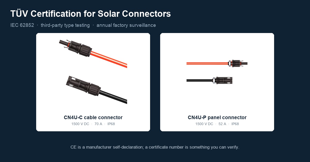
IEC 62852:2014, Connectors for DC-application in photovoltaic systems — Safety requirements and tests, is the reference standard for PV DC connectors in Europe and in most markets outside North America. A TÜV certificate against it is issued by a third-party body — TÜV Rheinland, TÜV SÜD or TÜV Nord — after a defined sequence: type testing of the design, an initial factory inspection, and annual surveillance of production control for as long as the certificate stays valid.
Three consequences follow from that structure, and all three matter at the purchasing stage.
First, the certificate is a type test. It qualifies a design, not a shipment. The design is defined by the type designation, the rated voltage and current, the conductor cross-section range, and the cable construction listed in the schedule. A part that fits the same housing but falls outside the listed cross-section range is not covered by it.
Second, the annual factory audit is what keeps the type test meaningful. Without surveillance of production control, a type test certifies a sample that was made once. This is the substantive difference between certification and a one-off test report, and it is the part that is easiest to skip.
Third, the certificate is only as good as the match between its scope and the part on the pallet. The check is mechanical: certificate number, issuing body, type designation, and the ratings and cable range in the schedule, compared against the part number and the cable actually being crimped.
2. Temperature rise: the 45 K limit
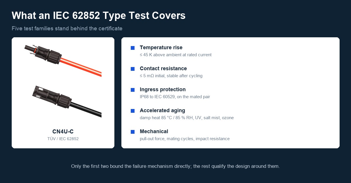
At rated current, the temperature rise measured at the contact must not exceed 45 K above ambient. The criterion is carried into IEC 62852 from IEC 61984, the general connector safety standard it builds on.
The number matters because of where the connector sits. A module junction box can reach 60–70 °C on a hot roof, and a 45 K rise on top of that puts the contact close to the 90 °C continuous rating of the XLPO insulation on the cable pressed into the same gland. Connector heating is not an abstract margin; it is the difference between a joint that stabilises and one that creeps upward.
Two conditions attach to that 45 K figure, and both are easy to lose in the field. The test is run with the conductor cross-section and cable construction named in the certificate, and with a crimp made to the manufacturer's specification. Change either one — a smaller conductor, a different cable outside diameter, a die from a different tooling set — and the measured rise no longer describes the installed joint.
3. Contact resistance, plating and spring force
Contact resistance is the number that connects the certificate to the failure mechanism. IEC 62852 bounds it — initial values for a mated pair are typically specified at or below 5 mΩ — and, more importantly, requires it to stay within limits after the mechanical and thermal cycling sequence, not only at the start.
What holds that resistance stable is the contact system: the plating on the contact surface and the normal force the spring geometry applies across it. Tin and silver plating over a copper alloy both appear in certified designs. What the standard tests is not a plating thickness in microns but the electrical consequence of losing it. Fretting — micrometre-scale movement at the interface driven by thermal cycling — wears through plating, exposes the base alloy to oxidation and pushes resistance up. A contact that starts at 3 mΩ and drifts to 15 mΩ dissipates five times the heat at the same current.
Because resistance is measured after the aging and cycling sequence, a connector that passes has demonstrated that its plating and spring force survive that sequence. It has not demonstrated survival of a mating interface it was never tested against, which is the subject of section 8.
4. IP68 and what it does not cover
IEC 62852 requires the mated connector to meet IP68 under IEC 60529 / EN 60529 — dust-tight, plus protection against continuous immersion under conditions more severe than the 30 minutes at 1 m that define IP67. The severity is set by agreement with the manufacturer rather than fixed by the code, so the depth and duration that matter are the ones on the certificate, not the two digits alone.
Two limits are worth stating plainly. IP68 on a connector describes the mated pair, not an unmated half; an unmated connector on a live string end relies on a sealing cap, which is a separate part with its own rating. And the seal is a component with a service life. The gland compresses against the cable sheath, so if the cable outside diameter falls outside the range the connector was type-tested with, the seal does not compress to the designed degree regardless of what the housing is marked.
5. Accelerated aging: what "25 years" does and does not mean
The durability part of IEC 62852 is an accelerated sequence: damp heat at 85 °C and 85 % relative humidity (IEC 60068-2-78), thermal cycling and thermal shock, salt mist where the application calls for it, ozone resistance, and UV exposure of the polymeric housing. The electrical measurements — contact resistance, dielectric strength — are taken after the sequence, not instead of it.
No part of this runs for 25 years, and no standard claims to compress 25 years into a chamber cycle. What the sequence does is load the dominant degradation mechanisms harder than the field does, so a design with no margin fails quickly in the laboratory. The 25-year design-life figure used across PV comes from somewhere else: thermal endurance data on the insulating materials, extrapolated to a temperature index under the EN 60216 / IEC 60216 series, supported by these accelerated cycles for the mechanisms thermal endurance does not capture.
Reading a certificate as "tested for 25 years" overstates it. Reading it as "the design has demonstrated margin against the mechanisms that actually kill connectors" is what the evidence supports.
6. Mechanical tests: pull-out, mating cycles, impact
The mechanical sequence covers the ways a joint is loaded in service and during installation. Pull-out force is measured on the cable-to-connector joint and on the mated pair, which is what keeps a connector from separating under the tension of a run pulled tight on a hot afternoon and contracting overnight. Mating-cycle durability runs the connector through repeated mating and unmating with resistance measured afterwards, so the spring geometry has to survive service access, not just first assembly. Impact and cold-impact tests cover handling at low temperature, when housing polymers are least forgiving.
The crimp sits inside this boundary. A connector is type-tested as an assembly with a specified conductor and a specified crimp geometry; the tensile strength of that crimp is part of what the certificate covers, and a crimp made with an unmatched die will not produce a gas-tight joint. Calibrated tooling and periodic pull-test sampling are what keep field crimps inside the tested envelope. The production side of that is described on the PV connector manufacturing and quality page.
7. CE, the TÜV mark, "TÜV tested" and UL 6703
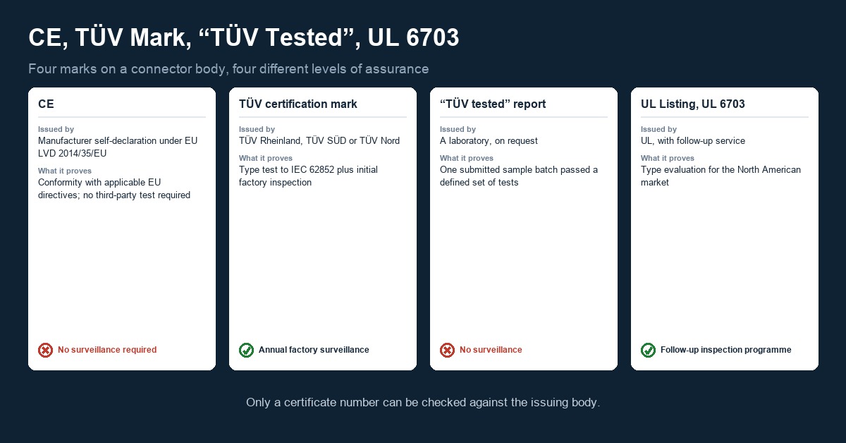
The marks printed on a connector body are not equivalent, and the gap between them is where uncertified product enters projects.
| Mark | Issued by | What it proves | Surveillance |
|---|---|---|---|
| CE | Manufacturer self-declaration under EU Low Voltage Directive 2014/35/EU | Conformity with the essential requirements of the applicable directives; no third-party test required | None required |
| TÜV certification mark | TÜV Rheinland, TÜV SÜD, TÜV Nord | Type test to IEC 62852 plus initial factory inspection | Annual factory surveillance |
| "TÜV tested" / test report | A laboratory, on request | One submitted sample batch passed a defined set of tests | None |
| UL Listing, UL 6703 | UL, with follow-up service | Type evaluation to UL 6703 for the North American market | Follow-up inspection programme |
The distinction between the second and third rows is the one that decides most arguments. A test report tells you that a sample submitted once passed. A certification tells you that the design passed and that the factory making it is audited for consistency. Both documents can carry the same logo.
For North America the reference is UL 6703 for connectors, with UL 4703 for PV wire. IEC and UL marks are not interchangeable — they are written against different supply and installation assumptions — but they address the same failure modes, and a project in the US or Canada needs the UL listing regardless of what the connector carries elsewhere.
8. Cross-brand mating: what intermateability does not cover
This is the most consequential misreading of IEC 62852 in connector sourcing. The standard's intermateability requirement is scoped to connectors of the same type, generation and keying — the same contact geometry and housing interface. It is a requirement on a family of identical parts, not a licence to mate brand A with brand B.
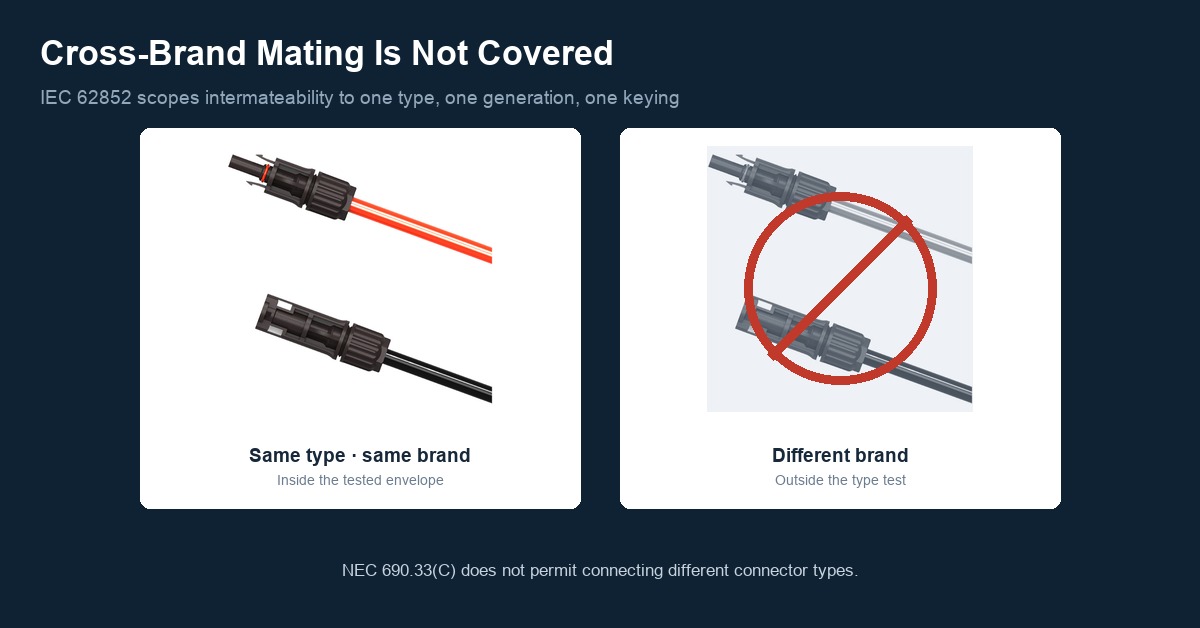
The engineering reason is dimensional. Contact-spring force and housing tolerance differ between manufacturers at the micrometre scale, and each is set to work with that manufacturer's own mating half. Mating across brands leaves the contact interface loaded differently from either design intent, which is the condition that produces fretting and resistance drift at the joint — the drift described in section 3, arriving early.
The code position is explicit. NEC 690.33(C) does not permit connecting different connector types, and Stäubli, which originated the MC4 interface, along with many EPCs, advises against mixing brands even where both halves carry a TÜV or UL mark. The practical rule is to standardise on one connector system across the string and the array, and to handle an unavoidable transition between systems with a listed adapter or a rated enclosure transition rather than a forced field mating. The interface question is treated at length in the MC4-compatible connector guide and the PV connector standards page.
9. Why the certificate matters downstream
Certification is a safety question and a project-viability question at the same time. Technical due diligence by EPCs and developers on commercial and utility work routinely requires certified balance-of-system components, and a connector with no TÜV or UL evidence is the kind of item that surfaces in a document review late enough to be expensive. Where grid acceptance, insurance cover or project financing depends on that review, missing certification on a BOS component can hold it up.
There is also a direct code link in the US. NEC 690.11 requires DC arc-fault protection on PV systems whose DC circuits operate above 80 V, which covers essentially every commercial and utility string. Arc-fault devices interrupt an arc once it starts; they do not prevent the high-resistance joint that starts it. Connector selection, correct crimping and a single-brand mating plan lower the probability that a joint becomes the initiation point.
10. How a certified connector still fails
The failure chain is well established: contact resistance rises, I²R heating at the joint increases, the extra heat accelerates the oxidation and annealing that raise resistance further, the housing carbonizes, and the carbonized path supports an arc. TÜV type testing attacks the first link, by bounding initial resistance and requiring it to hold through the aging and cycling sequence. It does not cover the rest of the chain, because the rest of the chain is workmanship.
Field data reflects that split. German PV fire statistics covering 1995–2012 recorded 180 fires, 24 percent of which originated at a connector; wider European bankability reporting puts the connector share between 12 and 29 percent. In both datasets the traced causes cluster on installation and sourcing — poor crimping, mixed brands, and plating or spring force that never matched the tested design — rather than on the certified design itself. The limits of what a certificate does and does not prove are set out in the PV connector certification overview.
11. Completing the DC chain: the PV cable
A certified connector is half of the joint. The cable pressed into it carries the same current through the same thermal cycle, and the certification envelope of the connector is conditioned on the cable type and cross-section range named in its schedule.
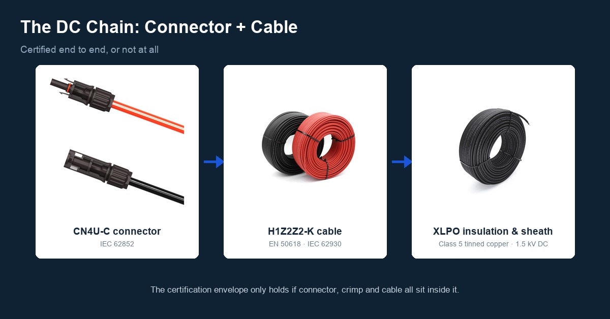
The specification to hold a cable supplier to:
- Designation and standard. H1Z2Z2-K to EN 50618:2014, or its international counterpart IEC 62930:2017. Both rate the cable at 1.0/1.0 kV AC and 1.5 kV DC. The older PV1-F construction to TÜV 2 PfG 1169 is rated 0.6/1.0 kV AC and 1.8 kV DC and is being displaced as 1500 V architectures spread.
- Insulation and sheath. XLPO — cross-linked halogen-free polyolefin. Not PVC, not PE, not TPE. XLPO carries the UV, ozone and flame performance the DC side needs, with low smoke and no halogen acid gas.
- Conductor. IEC 60228 Class 5 tinned copper, fine-stranded, matched to the crimp terminal the connector was tested with.
- Temperature. Service range −40 °C to +90 °C, with a maximum conductor temperature of +120 °C for 20,000 h.
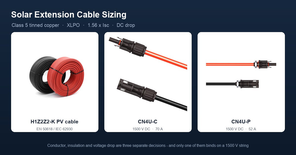
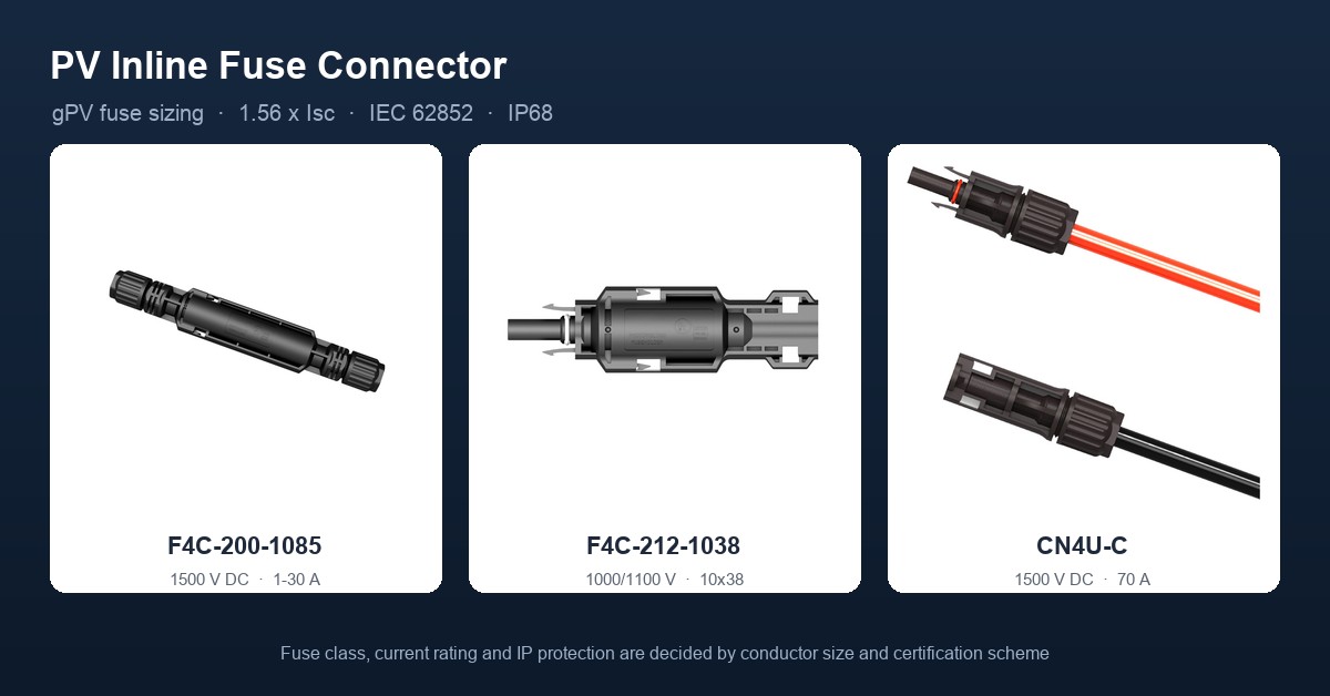
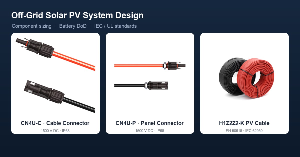
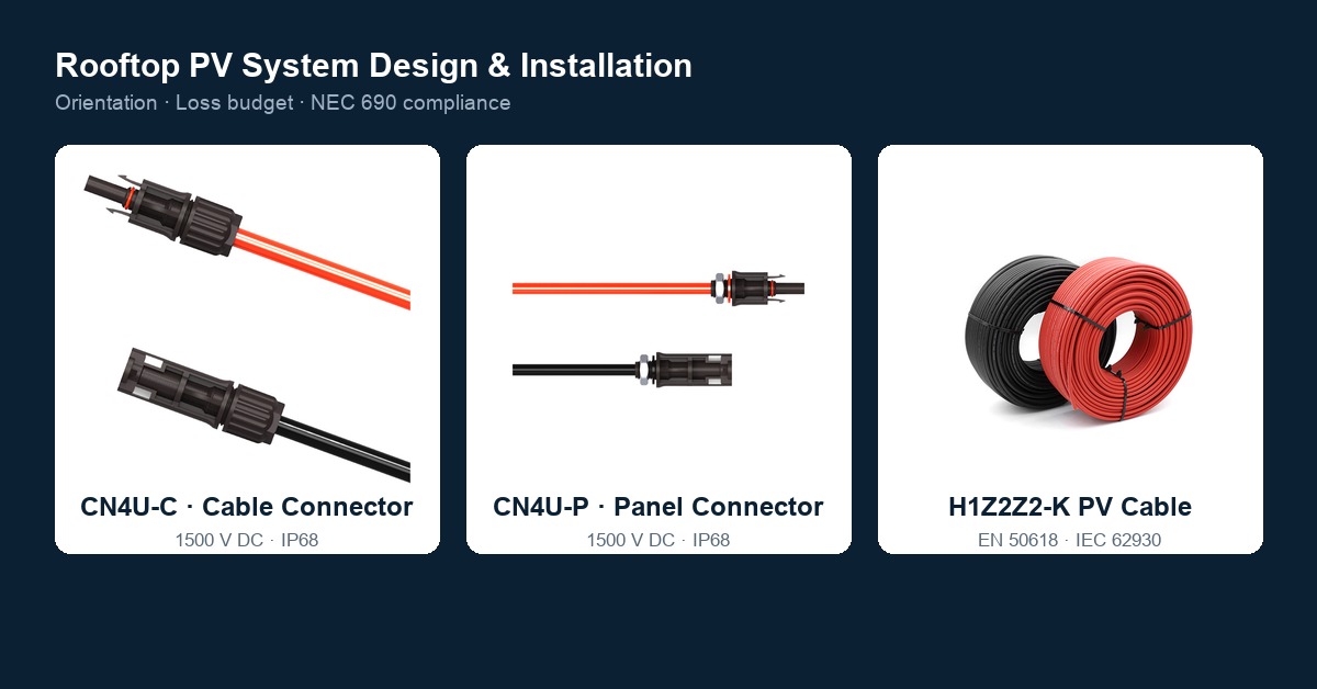
Mating a certified connector to an uncertified PVC cable inherits every failure mode of that cable, and it also takes the assembly outside the tested envelope, because the gland seal and the crimp were both qualified against a different sheath. Treasol supplies EN 50618 / IEC 62930 certified H1Z2Z2-K PV cable in the same sourcing system as the CN4U-C cable connector and the CN4U-P panel connector, so the DC run stays inside one certification envelope from module to combiner. The sizing and construction logic is covered in the solar PV cable guide.
12. Procurement checklist
- Ask for the certificate number, the issuing body and the scope — type designation, rated voltage and current, conductor cross-section range, and the cable construction the connector was tested with. A "TÜV tested" report is not a certificate.
- Match the cable: H1Z2Z2-K to EN 50618 / IEC 62930, XLPO insulation, Class 5 tinned copper, and a cross-section inside the connector's certified range.
- Standardise on one connector system for the whole array and document the mating plan, including how any transition between systems will be made.
- Verify crimp tooling and installer training, and sample pull-test crimps on site. A certified connector crimped with an unmatched die is no longer the certified assembly.
FAQ
Is CE marking enough for solar connectors?
No. CE is a manufacturer self-declaration under the EU Low Voltage Directive and does not require third-party testing. TÜV certification adds independent type testing plus annual factory surveillance.
Does TÜV certification allow mixing connector brands?
No. IEC 62852 intermateability applies only within the same type, generation, and keying. NEC 690.33(C) prohibits mixing connector types, and major manufacturers advise against cross-brand mating regardless of certification.
What standard covers PV connectors in North America?
UL 6703. It is the US/Canada equivalent of IEC 62852 and is required for NEC-compliant installations; TÜV/IEC and UL marks are not interchangeable.
Which cable goes with a TÜV-certified PV connector?
H1Z2Z2-K cable to EN 50618 / IEC 62930, XLPO-insulated, with an IEC 60228 Class 5 tinned copper conductor. Mating a certified connector to an uncertified PVC cable breaks the DC safety chain.
References
- IEC 62852:2014 — Connectors for DC-application in photovoltaic systems — Safety requirements and tests.
- IEC 61984 — Connectors — Safety requirements and tests; source of the 45 K temperature-rise criterion.
- IEC 60529 / EN 60529 — Degrees of protection provided by enclosures (IP code; IP68 is defined by agreement and is more severe than IP67).
- IEC 60068-2-78 — Environmental testing; damp heat, steady state (85 °C / 85 % RH).
- EN 50396 / HD 605, EN ISO 4892-3, IEC 60068-2-52 — Ozone resistance, accelerated laboratory weathering and salt mist methods used in the aging sequence.
- EN 60216 / IEC 60216 — Thermal endurance properties of insulating materials; basis for long-term temperature indices.
- IEC 62930:2017 — Electric cables for photovoltaic systems with a voltage rating of 1.5 kV DC.
- EN 50618:2014 — Electric cables for photovoltaic systems (H1Z2Z2-K).
- IEC 60228 — Conductors of insulated cables (Class 5 flexible tinned copper).
- UL 6703 — Standard for Connectors for Use in Photovoltaic Systems; UL 4703 — Photovoltaic Wire.
- NFPA 70 (NEC) 690.33(C) connector mating; NEC 690.11 DC arc-fault protection.
- German PV fire statistics, 1995–2012: 180 fires, 24 percent originating at connectors. European bankability reporting on PV fire causes: 12 to 29 percent attributed to connectors. NREL field reliability and O&M data on connector failures traced to crimp quality, mixed brands and plating.
Prepared by Treasun New Energy Technology Co., Ltd — manufacturer of MC4-compatible PV connectors, fuse connectors, junction boxes, wiring harnesses and H1Z2Z2-K photovoltaic cable.