Off-Grid Solar PV System Design: Component Sizing, Battery Selection and Safety
An off-grid photovoltaic system is a self-contained power plant. Unlike a grid-tied array, it cannot fall back on the utility when the sun is low or a load spikes, so every component has to be sized for the worst week of the year rather than the best hour. The design objective is not maximum yield per dollar; it is reliable supply at the lowest sustainable cost. That single difference changes how modules, batteries, controllers, inverters and cables are selected.
This guide covers the design inputs, the three typical system scales, the function and governing standard of each component, and the safety and commissioning checks that separate a dependable installation from a premature failure.
1. Design inputs you must fix first
Before selecting any hardware, four parameters define the whole system:
- Load power (W) — the running wattage of every AC and DC consumer, separated by type: resistive (heaters, incandescent lighting), inductive (motors, compressors, pumps) and capacitive (switch-mode electronics).
- Daily energy (Wh/day) — load power × hours of use, summed across all loads. Measure or log it where possible; estimates are where off-grid systems start to drift.
- Autonomy (days) — how many consecutive cloudy days the battery must cover without meaningful solar input. One to three days is typical; remote telecom sites often specify five.
- Site resource — average daily peak-sun hours (kWh/m²/day) for the worst month of the year, not the annual average, plus the optimal tilt for the latitude.
Only with these four numbers can battery capacity, array size and controller current be calculated. A common mistake is to size the inverter to the module nameplate and the battery to a vague "feels right" figure; both lead to chronic under-performance or damaged components.
2. System voltage: pick it before anything else
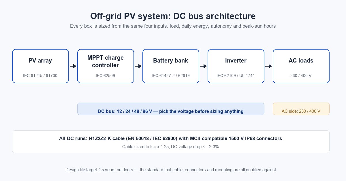
Off-grid systems rarely operate at grid voltage. They run on a DC bus — typically 12, 24, 48, 96 V or higher for large plants — which the inverter then steps up to 230/400 V AC (120/240 V in North America).
| Scale | Typical DC bus | Rationale |
|---|---|---|
| < 1 kW, lighting and phone charging | 12–24 V | Lowest cost, simple wiring |
| 1–10 kW residential | 48 V | Best balance of current and component cost |
| 10–60 kW commercial | 48–96 V | Lower currents, thinner cables |
| > 60 kW microgrid | 96–480 V, often AC-coupled | Matches genset and grid interfaces |
Higher bus voltage means lower current for the same power, which reduces cable cross-section and copper loss (P = I²R). For anything above a few kilowatts, 48 V is the practical floor.
3. Three typical off-grid scales
3.1 Low-cost small system (< 1 kW, < 5 kWh/day)
Typical users are off-grid households, remote cabins, herding settlements and lighting-plus-phone-charging installations. Loads are small and the priority is low price with acceptable reliability.
- An integrated PWM controller + modified-sine inverter unit keeps cost and wiring minimal and runs bulbs, small TVs and fans without issue.
- Be aware of the trade: PWM clamps the array to battery voltage and typically harvests only 75–80% of available PV energy. Where modules are expensive or sun is marginal, even a small MPPT stage pays for itself quickly.
- Lead-acid and lead-carbon batteries dominate this segment on cost.
3.2 Small-to-medium practical system (< 20 kW, < 50 kWh/day)
Users include island residents, medium fishing vessels, remote scenic sites and telecom backup power. Loads extend to air conditioning, pumps and other motor-driven equipment, which changes the controller and inverter choices:
- Few inductive loads → MPPT + high-frequency isolated inverter: lighter and cheaper.
- Many inductive loads → MPPT + low-frequency (transformer-based) inverter, which carries shock loads far better.
- Long runtime, low peak power → separate charge controller with a smaller inverter to cut array cost.
- Short high-power peaks → integrated controller/inverter unit for simpler wiring.
Inductive-load rule: motor and compressor inrush runs 3–5× rated current, while a typical off-grid inverter sustains only 150–200% for a few seconds. Size the inverter at at least 2× the inductive load — a 2P (2 × 750 W) air conditioner therefore calls for a 3 kVA or larger unit.
3.3 Medium-to-large and microgrid (> 20 kW)
Found in industry, resorts and areas with frequent outages or no grid at all; installations commonly run 20–250 kW and scale beyond that.
- 20–60 kW: parallel single-phase inverters (flexible, and the plant survives one unit failing) or a single medium inverter, optionally paired with a diesel genset as a hybrid to slash battery capacity.
- Above 60 kW: choose between DC coupling (PV → charge controller → DC bus → inverter) and AC coupling (PV → grid-tie inverter → AC bus → bidirectional inverter → battery). AC coupling dominates microgrids because it mixes PV, wind, genset and storage behind a common AC bus without redesigning the DC side.
- Above 250 kW: bidirectional storage converters plus grid-forming inverters, integrating wind and diesel alongside PV.
4. Component selection with standards
4.1 PV modules — IEC 61215 / IEC 61730
Off-grid sites usually have ample land, so module conversion efficiency matters less than it does on a constrained rooftop. Conventional crystalline modules are the default; qualify them to IEC 61215 (design qualification) and IEC 61730 (safety).
4.2 Mounting — aluminium or hot-dip galvanized C-steel
Both are standard. For hot-dip galvanized C-steel, verify the zinc coating thickness against the atmospheric corrosivity class of the site (ISO 9223 categories, coatings typically to ISO 1461). An under-spec coating will not reach a 20-year service life, especially in coastal or high-humidity environments — the same reasoning that makes tinned copper non-negotiable in the DC wiring, as covered below.
4.3 Charge controller — IEC 62509
The controller prevents battery over-charge and over-discharge. Two technologies are in service:
- PWM: simple and cheap, harvesting roughly 75–80% of available array energy; being displaced.
- MPPT: tracks the array's true maximum power point with 95–99% conversion efficiency and extracts more energy in cold, low-light or partially shaded conditions. It is the default for new off-grid systems.
Sizing (IEC 62509 basis): the controller's maximum PV input current must exceed the array short-circuit current with a 25% margin — the same 1.25 factor NEC 690.8 applies to PV circuit conductors:
I_controller ≥ I_sc_array × 1.25
A 48 V / 30 A controller, for example, must not see more than 30 A from the array, or it will be damaged.
4.4 Battery — the heart of the system
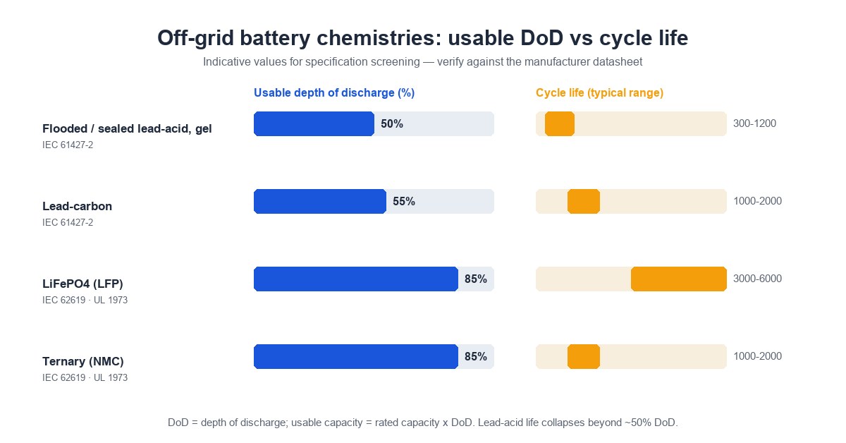
| Chemistry | DoD* | Cycles | Notes | Standard |
|---|---|---|---|---|
| Flooded / sealed lead-acid, gel | 50% | 300–1200 | Cheapest; needs ventilation (H₂ off-gassing) | IEC 61427-2 |
| Lead-carbon | 50–60% | 1000–2000 | Longer cycle life than lead-acid at modest extra cost | IEC 61427-2 |
| LiFePO₄ (LFP) | 80–90% | 3000–6000 | High energy density, BMS required, thermally stable | IEC 62619, IEC 63056, UL 1973 |
| Ternary (NMC) | 80–90% | 1000–2000 | Highest energy density, weaker thermal margin | IEC 62619, UL 1973 |
*DoD = depth of discharge; usable capacity = rated capacity × DoD.
Battery capacity formula:
Battery Ah = (Daily load Wh × Autonomy days) / (System V × DoD × inverter/charge efficiency)
Lead-acid must be confined to roughly 50% DoD or cycle life collapses; LFP tolerates 80–90%, which is why a smaller LFP bank often replaces a much larger lead-acid one. Lead-acid banks need ventilation and acid containment; lithium banks need a BMS for cell balancing, over-current protection and thermal cutoff. Note that the "2–3× the cost of lead-acid" figure quoted in older references has narrowed sharply as LFP production has scaled — re-cost that comparison against current quotes before committing to a chemistry.
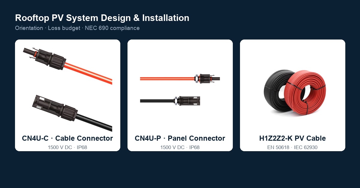
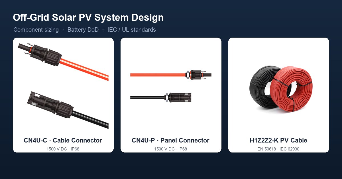
4.5 PV cable — H1Z2Z2-K
Photovoltaic DC cable is built to EN 50618 / IEC 62930, designation H1Z2Z2-K: cross-linked halogen-free polyolefin (XLPO) insulation and sheath over a tinned Class-5 copper conductor (IEC 60228). The ratings a specifier can cite from the standard:
- Voltage: 1500 V DC.
- Temperature: 90 °C continuous conductor temperature; 120 °C as the higher temperature class; a defined short-circuit withstand at 250 °C. The 120 °C figure is a rating limit, not a normal operating temperature — size the run as if 90 °C applies.
- Design life: 25 years outdoors, demonstrated by accelerated UV and ozone exposure, cold-bend, flame-retardant (IEC 60332-1-2), halogen-free (IEC 60754) and low-smoke (IEC 61034) testing.
- XLPO cross-linking converts the polymer from thermoplastic to thermoset — that is what delivers the UV, ozone and heat resistance plain PVC cannot. Lifecycle multipliers such as "8× ordinary cable" do not appear in any cable standard and cannot be verified; the ratings above are the citable ones.
Cable sizing for off-grid DC runs follows the same rule as any PV DC circuit:
I_cable ≥ I_sc × 1.25   (current capacity with safety factor)
Voltage drop ≤ 2–3% of system voltage on the DC side
Tinned copper is specified precisely because off-grid sites are often coastal, humid or polluted, where bare copper corrodes at the terminations first. Treasol's H1Z2Z2-K solar PV cable (category: solar PV cable) is built to this standard and pairs with MC4-compatible connectors. In North America, where EN 50618 is less commonly invoked, the equivalent conductor is PV wire listed to UL 4703.
4.6 Off-grid inverter — IEC 62109 / UL 1741
Select on two axes:
- Load type: resistive, inductive (3–5× inrush) or capacitive. Size the continuous rating to total running load and the surge rating to the largest inductive start, applying the ≥ 2× inductive rule from section 3.2.
- DC side: the built-in charger is almost always MPPT today. Size charger power from local peak-sun hours and the required recharge time — a bank should return to full within one average day, or it lives in a partially discharged state that shortens lead-acid life in particular.
Qualify inverters to IEC 62109-1/-2 (safety of power converters) and, for North America, UL 1741.
4.7 Connectors, fuses and branching
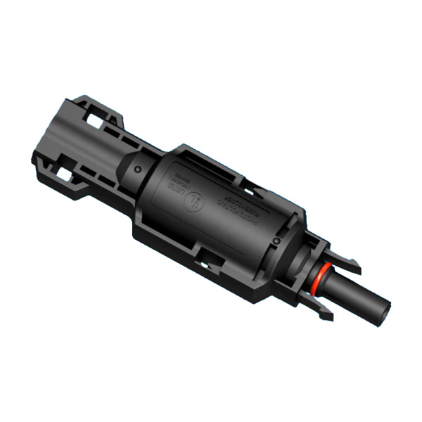
Every DC junction is a potential failure point, and an off-grid plant has more of them than a grid-tied one because strings, arrays and battery circuits converge. Use MC4-compatible, 1500 V-rated, IP68 connectors — the CN4U-C cable connector and CN4U-P panel connector — and keep one connector brand end-to-end. Cross-brand mating violates the intermatability requirements of NEC 690.33 / UL 6703 (and IEC 62852 internationally) and is a leading cause of field arc faults; the MC4-compatible connector guide covers the mating rules in detail.
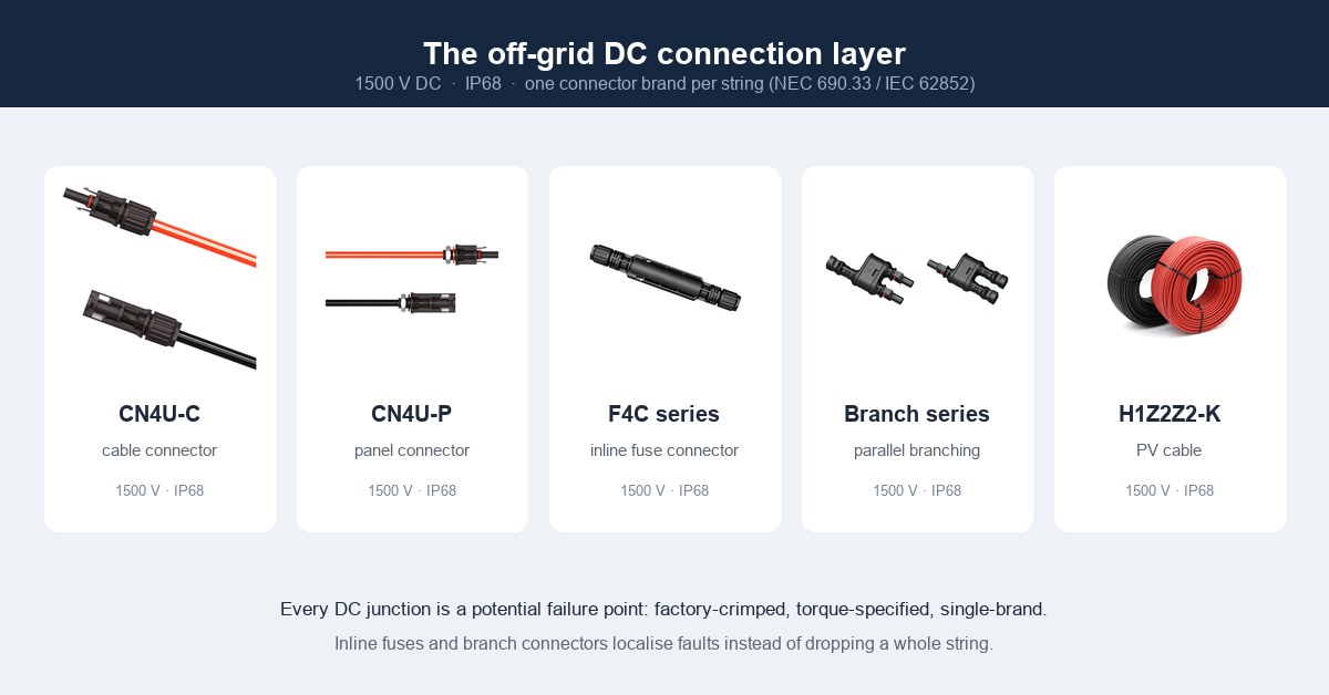
Inline fuses and branch connectors localise faults to the affected string or branch instead of taking the whole array down — on an off-grid plant with no grid to fall back on, that distinction matters more than it does elsewhere. Where strings pass through combiners, the F4C inline fuse connector keeps overcurrent protection at the connector level.
5. Safety and commissioning
- Ventilation and containment: lead-acid banks off-gas hydrogen — enclose and vent them per code. Lithium banks need BMS supervision and thermal management, and cells must ship and store per UN 38.3.
- Disconnects and isolation: every DC and AC section needs a labelled, accessible disconnect (NEC 690.13 / IEC 60364-7-712).
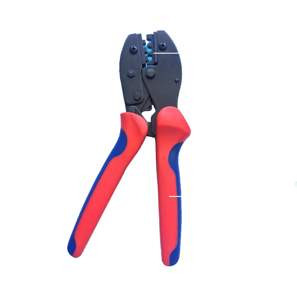
- Arc-fault and ground-fault protection: DC arc-fault protection is mandatory in many jurisdictions. DC arcs do not self-extinguish, so the passive defence is equally important: gas-tight, torque-specified crimps. The MC4 crimping tool and matched dies produce the crimp the connector standard assumes; field-crimped joints made with pliers do not.
- Commissioning: verify polarity, string open-circuit voltage and short-circuit current against design, measure insulation resistance and run a functional load test to IEC 62446 before handover.
Relevant code anchors: IEC 60364-7-712 (PV electrical installations), IEC 62446 (commissioning and maintenance), NEC Article 690 (PV), NEC Article 480 (storage batteries) and 706 (energy storage systems); module racking to UL 2703.
6. Conclusion
A reliable off-grid PV system is an exercise in matching four design inputs — load, daily energy, autonomy and sun — to a consistent DC bus, then selecting each component against its own standard: IEC 62509 controllers, IEC 62109 inverters, IEC 61427-2 / 62619 batteries, and EN 50618 / IEC 62930 cable. Respect depth-of-discharge and ventilation limits, keep connector brands consistent, and the result is a plant that runs its full 25-year design life instead of failing in year three.
Treasol supplies the connection layer of that plant — H1Z2Z2-K PV cable, MC4-compatible connectors and the manufacturing quality system behind them — built and tested to the standards referenced in this guide.
7. Products referenced in this guide
- H1Z2Z2-K solar PV cable (EN 50618 / IEC 62930, 1500 V DC, tinned copper)
- Solar PV cable category
- CN4U-C MC4-compatible cable connector (1500 V, IP68)
- CN4U-P MC4-compatible panel connector (1500 V, IP68)
- F4C-200-1085 inline fuse connector
- Branch connector series
- MC4-compatible solar connector guide
- PV connector manufacturing process
FAQ
How do I size an off-grid battery bank?
Compute daily load in Wh, multiply by autonomy days, then divide by (system voltage × allowable depth of discharge × efficiency). Use 50% DoD for lead-acid, 80–90% for LiFePO₄.
MPPT or PWM for an off-grid controller?
MPPT, almost always. It harvests 95–99% of available PV energy versus about 75–80% for PWM, and performs better in cold or low-light conditions. Size it to Isc × 1.25.
What DC system voltage should I choose?
Match voltage to scale: 12–24 V for tiny loads, 48 V for most residential off-grid, 96 V and above for commercial and microgrids, to keep currents and cable sizes manageable.
Can I use a standard car battery in an off-grid system?
No. Car (starter) batteries are built for short, high-current bursts, not deep discharge. Use deep-cycle lead-acid, lead-carbon or LiFePO₄ designed for cyclic service.
How do I size the inverter for air conditioners and pumps?
Size continuous rating to total running load and surge to the largest inductive start (3–5×). As a rule of thumb, the inverter should be at least 2× the inductive load's running power.
What cable is correct for off-grid PV DC wiring?
H1Z2Z2-K (EN 50618 / IEC 62930): XLPO, tinned copper, 90 °C continuous / 120 °C class, 25-year outdoor life. Size by Isc × 1.25 with DC voltage drop of 2–3% or less.
References
- IEC 61215 — Crystalline silicon terrestrial PV modules: design qualification and type approval.
- IEC 61730 — PV module safety qualification.
- IEC 62509 — PV DC charge controllers: general requirements and test procedures.
- IEC 62109-1 / -2 — Safety of power converters for use in PV power systems.
- IEC 61427-2 — Secondary cells and batteries for renewable energy storage systems.
- IEC 62619 / IEC 63056 — Safety requirements for industrial and stationary lithium cells and batteries.
- UL 1973 — Batteries for stationary and light electric rail applications.
- EN 50618 / IEC 62930 — Photovoltaic cable (H1Z2Z2-K), 1500 V DC.
- IEC 60228 — Conductors of insulated cables (Class 5 flexible conductor).
- IEC 60332-1-2, IEC 60754, IEC 61034 — Flame retardancy, halogen-free and low-smoke cable tests.
- UL 4703 — Photovoltaic wire (North American equivalent conductor).
- IEC 62852 — Connectors for DC applications in photovoltaic systems; UL 6703 — PV connectors (North America).
- IEC 60364-7-712 — Electrical installations: PV power supply systems.
- IEC 62446 — PV systems: requirements for testing, documentation and maintenance.
- UL 2703 — Rack mounting systems for PV modules.
- ISO 1461 — Hot dip galvanized coatings on iron and steel articles; ISO 9223 — Corrosivity of atmospheres.
- UN 38.3 — Transport of dangerous goods: lithium battery tests.
- NFPA 70, National Electrical Code — Article 690 (Solar Photovoltaic Systems), Article 480 (Storage Batteries), Article 706 (Energy Storage Systems).
Prepared by Treasun New Energy Technology Co., Ltd — manufacturer of MC4-compatible PV connectors and H1Z2Z2-K photovoltaic cable.