Rooftop PV System Design & Installation: Orientation, Loss Budget and NEC 690 Compliance
A rooftop PV system is decided twice: once on the design table, and again every day it runs for the next 25 years. Most under-performance is locked in at design — a few degrees of wrong tilt, a string crossed by morning shade, or a connector assembled without torque. This guide skips the generic checklist and covers what actually moves yield and what the codes require: orientation and tilt, a realistic loss budget, string electrical design under NEC Article 690, structural and corrosion control, and grounding.
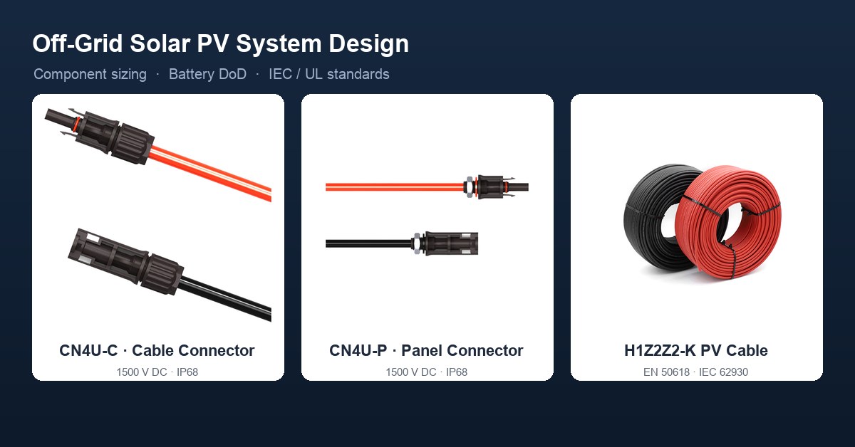
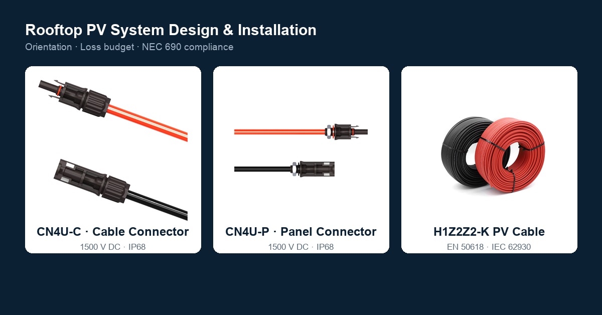
Treasol supplies 1500 V DC, IP68, MC4-compatible connectors and H1Z2Z2-K (EN 50618 / IEC 62930) photovoltaic cable for residential and commercial rooftops. Product links appear inline and in the references section.
1. Orientation and tilt: the parameters you cannot fix later
1.1 Azimuth
In the northern hemisphere, true south (azimuth 180°) maximises annual yield. The penalties are smaller than many assume:
| Orientation | Approx. annual yield vs. due south |
|---|---|
| South (180°) | 100% (reference) |
| Southeast / Southwest (135°–225°) | 95–98% |
| East / West (90° / 270°) | 85–90% |
| North (< 45° or > 315°) | 60–70% (avoid) |
East/west arrays shift production toward morning and evening peaks — often useful for self-consumption profiles even at a small annual penalty. These figures are validated by tools such as NREL's PVWatts and the AIA renewable-energy guidance.
1.2 Tilt
Set tilt near the site latitude for balanced year-round output (about 30–40° in mid-latitudes). A range of 15–40° performs well across most of the continental U.S.; steeper helps snow shedding in cold climates, flatter suits sunny southern regions. A tilt above 10° also enables rain self-cleaning, which reduces soiling loss. Flat roofs use ballasted or penetrated racking to reach the target tilt while keeping panels from shading one another.
1.3 Shade and mismatch
Even partial shade on one cell string drags the whole series string down to its level; bypass diodes help but do not remove the loss. Keep every module unshaded during peak sun hours (commonly cited as 9:00–16:00), and account for present and future shade — tree growth, neighbouring construction. Where shading is unavoidable, use module-level power electronics (MLPE — microinverters or DC optimizers) to isolate the affected modules.
2. The loss budget: why a "100 W" module delivers ~70 W
Nameplate watts are measured at STC (1000 W/m², 25 °C cell). Real operating output is lower after a stack of inefficiencies. A representative chain:
| Loss stage | Typical factor | Notes |
|---|---|---|
| Manufacturing / mismatch | ×0.97 | 1–2% array mismatch + tolerance |
| Cell temperature (operating ~45–65 °C) | ×0.88–0.92 | temperature coefficient, ~0.3–0.4 %/°C |
| Soiling (dust / pollen / bird) | ×0.95–0.98 | site- and season-dependent |
| DC wiring / I²R (cable + connector) | ×0.98 | minimise by correct gauge & short runs |
| Inverter conversion | ×0.94–0.96 | weighted, not peak |
A 100 W STC module therefore delivers roughly 68–76 W AC at the point of use under clear midday conditions — consistent with the ~68 W figure the original source cited, but now attributed to named, measurable stages rather than an unexplained product. Run NREL PVWatts with your actual azimuth, tilt and shading to turn this into an annual kWh estimate rather than a point-in-time guess.
3. Electrical design under NEC Article 690
3.1 String sizing
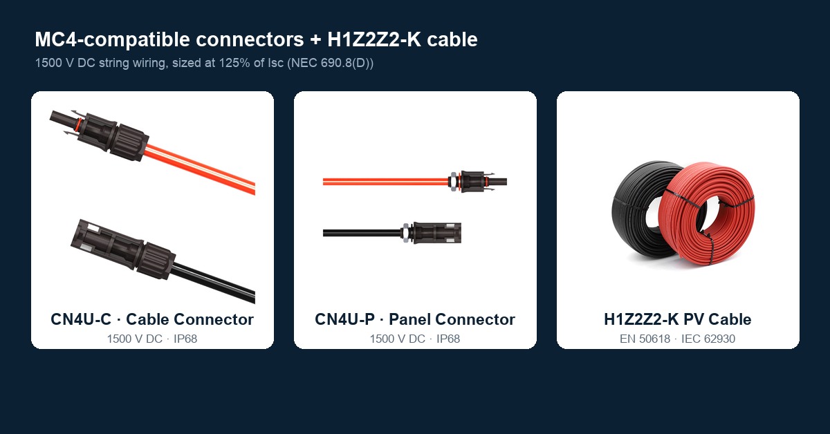
Size conductors and overcurrent protection at 125% of the string's short-circuit current (Isc) per NEC 690.8(D). Select cable gauge to keep DC voltage drop at or below ~2% (never exceeding 3%). Match the system voltage — 1000 V DC for most residential and 1500 V DC for larger commercial rooftops — and use connectors and cable rated for that voltage, such as CN4U-C MC4-compatible connectors and H1Z2Z2-K photovoltaic DC cable.
3.2 Inverter and DC/AC ratio
A DC/AC ratio of 1.2–1.5 is common: it overpanels the inverter so clipping only occurs during rare peak irradiance, raising annual energy without a proportionally larger (costlier) inverter. Confirm the inverter's maximum input voltage stays below the 1000 V / 1500 V limit across the coldest — and therefore highest-voltage — condition.
3.3 Required protective functions
- Overcurrent protection — NEC 690.9.
- Disconnect means — NEC 690.13, accessible and labelled.
- Ground-fault detection / interruption (GFDI) — NEC 690.41 for grounded systems.
- Rapid shutdown — NEC 690.12: on building-mounted systems, conductors must be reduced to controlled voltage within 30 seconds of activation (MLPE or a listed PV hazard control system).
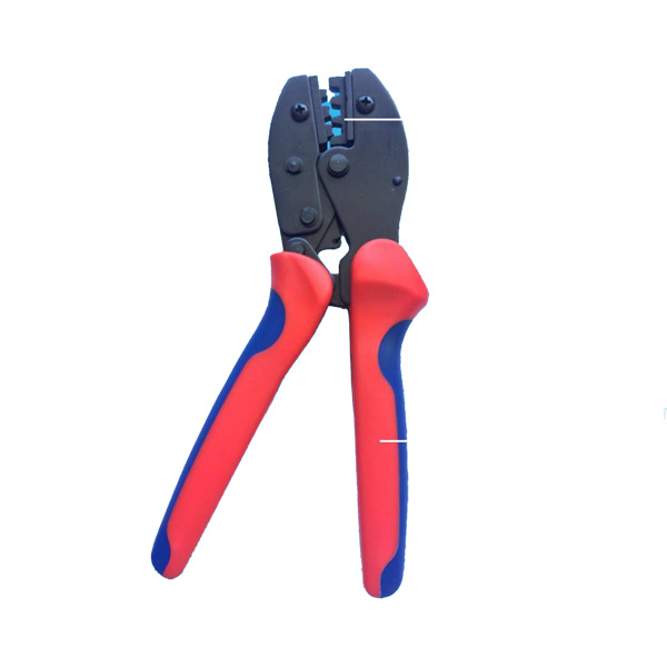
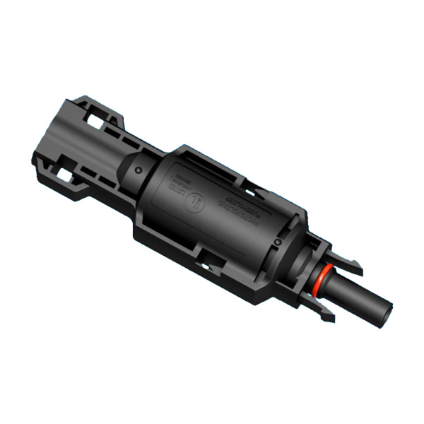
- Arc-fault / proper crimping — DC arcs do not self-extinguish; a gas-tight, torque-specified MC4 crimp is the field defence. CN4U-C is crimped to specification in the factory, and the MC4-compatible connector guide covers the mating rules.
4. Mounting, structure and fire code
- Roof load: a PV system adds roughly 3–6 lb/ft²; verify the roof structure (and wind uplift to ~120 mph) with an engineer before loading.
- Flashing, not sealant: roof penetrations require proper flashing integrated with the roofing system. Relying on polyurethane sealant alone voids many roof and module warranties and leaks.
- Ventilation air gap: maintain a gap (commonly ≥10 cm / 4 in) between the module backsheet and the roof to limit heat buildup and preserve fire classification.
- Fire setback / access pathway: maintain the code-required pathway (commonly an 18-inch / 3-foot clear aisle) for firefighter access per local adoption of NFPA 70 / IFC.
- Module certifications: specify modules tested to IEC 61215 (design qualification, 2400 Pa wind / 5400 Pa snow load class typical) and IEC 61730 (safety). Do not walk on or place loads on modules.
5. Materials and corrosion control
- Dissimilar metals: isolate aluminium from steel/iron with insulating spacers or washers to prevent galvanic corrosion; use stainless-steel fasteners throughout.
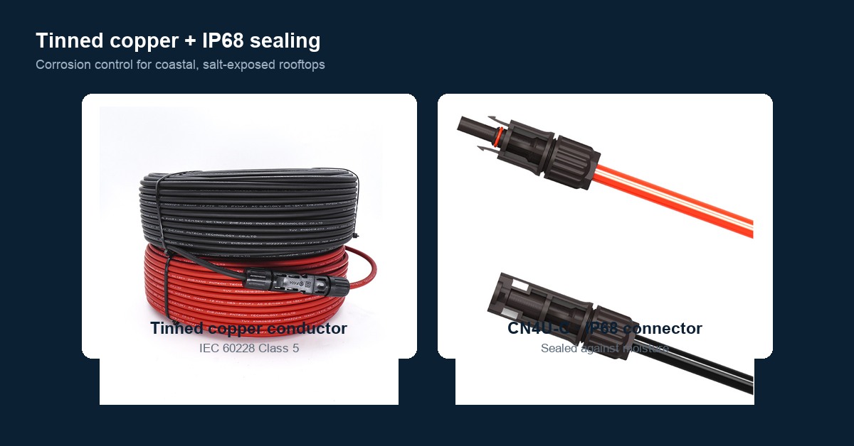
- Coastal environments: salt-laden air accelerates corrosion. Use tinned copper PV conductors (IEC 60228 Class 5) and corrosion-resistant connector contacts — the reason Treasol H1Z2Z2-K cable uses tinned copper and the CN4U-P panel connector and CN4U-C cable connector carry IP68 sealing.
- UV resistance: all exposed cable, ties and conduits must be sunlight-rated (standard PV wire is XLPO-jacketed per EN 50618 / IEC 62930; use UV-stabilised clips, not plain nylon).
6. Grounding (NEC Article 690)
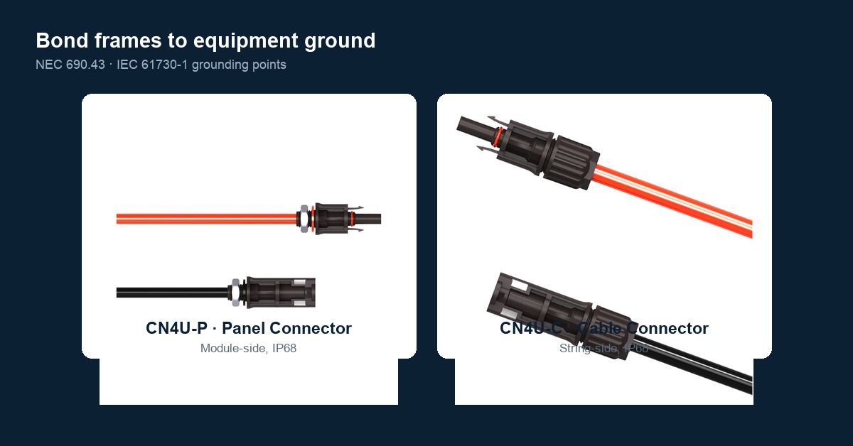
Bond all exposed conductive parts — module frames, racking, combiner and inverter enclosures — to an equipment grounding conductor per NEC 690.43 (system grounding per 690.41). Frame bonding typically uses 4–14 mm² copper at IEC 61730-1 marked points; in North America use hardware listed to UL 2703 / UL 467. Isolate frames from other metals to avoid galvanic corrosion, and never drill extra frame holes — it voids the module warranty.
7. Safety red lines
- Never work live. MC4 connectors are not load-break rated; de-energise and confirm zero current first.
- One connector brand per string (NEC 690.33 / UL 6703) — cross-brand mating is the leading field arc-fault cause, as the MC4-compatible connector guide explains.
- Energised DC is dangerous: under sun, a module produces current that rises with light. Cover modules or work in dark conditions, use insulated tools, and keep connectors dry and clean before mating.
- Rapid shutdown is mandatory on building-mounted systems.
8. Commissioning and O&M
- Verify string open-circuit voltage and short-circuit current against design at commissioning.
- Infrared-scan accessible connectors under ≥80% load annually (commercial) or biennially (residential); a joint running more than 10–20 °C above its neighbours is a pre-failure condition.
- Keep vegetation and shading trimmed; inspect flashing and mounting annually.
9. Treasol products referenced
- CN4U-C MC4-compatible cable/inline connector (1500 V, IP68)
- CN4U-P MC4-compatible panel connector (1500 V, IP68)
- H1Z2Z2-K photovoltaic DC cable (EN 50618 / IEC 62930, tinned copper)
- Solar PV cable category
- MC4-compatible solar connector guide
- PV connector manufacturing process
10. FAQ
What is the best tilt and orientation for a rooftop PV system?
In the northern hemisphere, face true south at a tilt near your site latitude (15–40° works for most of the U.S.). South yields 100%; SE/SW 95–98%; E/W 85–90%; north-facing 60–70% and is generally avoided.
Why does a 100 W panel only deliver about 70 W?
Nameplate is at STC (25 °C, 1000 W/m²). Real output loses ~3% to mismatch, ~8–12% to cell heating, several percent to soiling, ~2% to DC wiring, and ~4–6% to the inverter — landing near 68–76 W AC at midday.
How big should I size the PV string conductors?
Per NEC 690.8(D), size at 125% of the string Isc, keep DC voltage drop ≤2% (max 3%), and match the 1000 V or 1500 V system rating. Use tinned-copper PV wire (EN 50618 / IEC 62930).
Do I need rapid shutdown on a rooftop system?
Yes. For building-mounted systems, NEC 690.12 requires conductors to drop to controlled voltage within 30 seconds — typically via MLPE or a listed PV hazard control system.
Is sealant enough for roof penetrations?
No. Proper flashing integrated with the roofing system is required; sealant alone typically voids roof and module warranties and leaks. Maintain the code-required fire-access pathway and a ventilation air gap.
How do I prevent corrosion on a coastal rooftop array?
Isolate dissimilar metals, use stainless fasteners, specify tinned-copper PV conductors and IP68 connectors, and keep all exposed parts UV- and salt-rated.
11. Conclusion
Rooftop PV design is a chain of irreversible decisions: tilt and orientation set the annual ceiling, the loss budget sets realistic yield, NEC 690 sets the safety floor, and structure, corrosion control and grounding set the 25-year survival. Get the electrical sizing (Isc × 1.25, correct voltage class, rapid shutdown), the mechanical detail (flashing, air gap, fire pathway) and the connector discipline (one brand, gas-tight crimp, torque) right at design, and the system pays back for decades. Specify certified Treasol 1500 V MC4-compatible connectors and H1Z2Z2-K PV cable as the durable backbone.
Prepared by Treasun New Energy Technology Co., Ltd — manufacturer of MC4-compatible PV connectors and H1Z2Z2-K photovoltaic cable.
References
- AIA, Architect's Primer on Renewable Energy (2024) — orientation, tilt, shading, roof load and solar-ready design.
- NREL PVWatts — annual yield simulation by azimuth, tilt and shading.
- NFPA 70, National Electrical Code (NEC) Article 690 — 690.8(D) conductor sizing, 690.9 overcurrent, 690.13 disconnect, 690.33 connector intermating, 690.41 GFDI, 690.43 grounding, 690.12 rapid shutdown.
- IEC 61215 — Terrestrial PV module design qualification and type approval (mechanical load classes).
- IEC 61730-1 — PV module safety qualification (frame grounding points).
- IEC 62930 / EN 50618 — Cross-linked, halogen-free PV cable (H1Z2Z2-K), 1.5 kV DC.
- IEC 60228 — Conductors of insulated cables, Class 5 flexible conductor.
- UL 6703 / UL 2703 / UL 467 — Connectors; rack/grounding hardware for PV systems (North America).
- IEC 62852 — Connectors for DC-application in photovoltaic systems.